Because of its influence on weight and cost, accurately digitizing the wiring system is a priority when implementing a digital twin strategy in the automotive and transportation sectors. It’s also one of the most challenging aspects of this task.
In my last blog, I focused on the importance of a comprehensive and standardized data model as my first key requirement to meet this challenge.
Today I want to concentrate on the various aspects of the wiring system, and consider how different users expect to see different presentations and views of the related data.
Block 1: Connectivity and topology
Let´s see how a wiring system can be described digitally: The core of a KBL or VEC file is the product description of the wiring harness itself. This description can be broken down into connectivity and topology parts.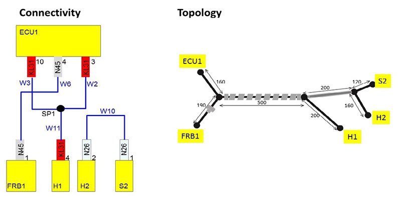
Connectivity describes the electrical from-to relationships – or which wires connect with which components, including all technical details. On the other hand, the topology defines the geometrical details – where the wires run in the vehicle, including electromechanical parts for wire protection like tapes, tubes or grommets.
In a KBL or VEC this information is modeled in a standardized XML file. However this XML can’t be read by a user directly, so a specialized viewer is required.
Because of its rich functionality, Zuken’s E3.HarnessAnalyzer has become the de facto-standard for this task. The connectivity, as well the topology information with all its details and relations, are shown in a data grid. In addition, this information is represented in a graphical format to satisfy the different needs of each user:
- For those who are mainly interested in connectivity, the tool can render a partial schematic out of the digital connectivity model.

- If the interest lies more with the geometrical part, then a 3D rendering of the KBL data may be the perfect choice.
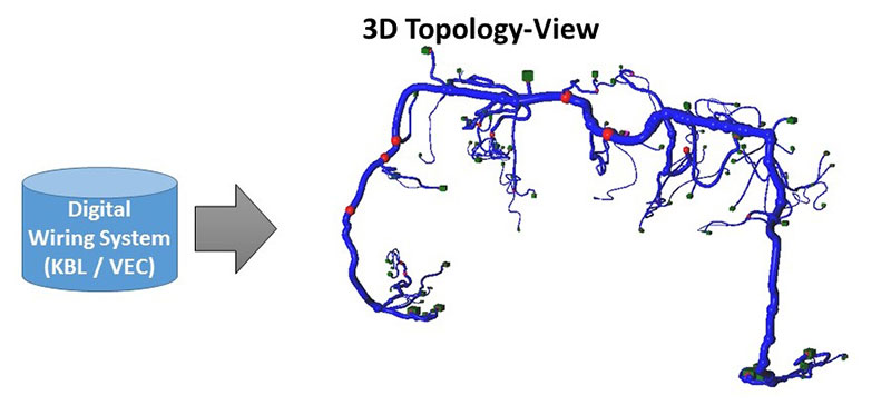
- But sometimes a 2D representation of the KBL data may be combined with the original harness drawing as a SVG, and can be the better choice for answering specific questions.
Block 2: Metadata, complexity and history
So, the digital data model KBL / VEC can describe the harness product completely, and a powerful viewer can make this design information easily understandable to different users to support their specific needs.
In addition to the pure design data, a KBL / VEC file can also carry a comprehensive set of metadata. The most important of these are related to complexity management, as wiring harness products are heavily variant related – often even in unique, customer-specific products. Depending on the method used, a KBL / VEC file can model a composite harness structure as well as a modular one (KSK). And this model description has to be distributed to the users via the powerful functionality of the viewer tool – such as updating the graphical views based on the vehicle-specific selection of KSK modules.
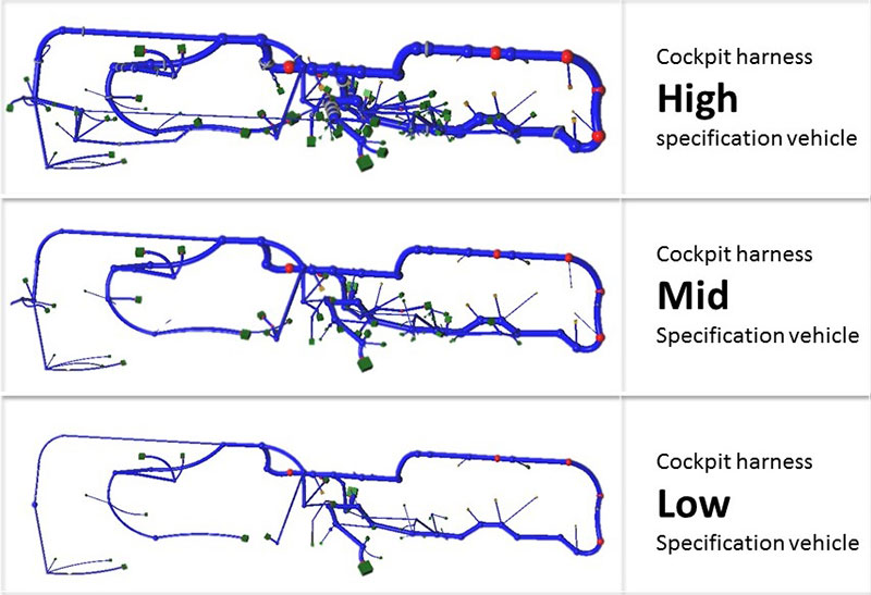
Of course, this filtering operation must be applied to all data grids and viewpoints.
In addition, KSK can transport history information – especially for the modules. Having a powerful viewer tool, the user can easily find out details about the current product version – such as who released it and when. And they can retrieve the history of a specific harness module.
Block 3: Release and version data, PLM model
The communication of metadata in KBL is outperformed by far when using the VEC format. VEC can contain the release and version data on every single object, so the user can acquire detailed information about any connector or terminal. As a result, VEC can also claim to cover a comprehensive PLM model for wiring system components.
Such a powerful data format requires not only a viewer to create benefits for the stakeholders in the process, but also powerful authoring tools and a dedicated data management solution. With Zuken’s popular E3.series electrical design tool, in combination with its dedicated data management tool, DS-E3, Zuken is well prepared to provide the full suite of tools for the whole process chain of digital wiring system development.
Also see:
Related Content

- Products

- Products
E3.series is a true concurrent electrical engineering environment supporting advanced requirements for electrical documentation, cabinet and wire harness design and manufacturing outputs.

- Blog
Because of its influence on weight and cost, accurately digitizing the wiring system is a priority when implementing a digital twin strategy in the automotive and transportation sectors. It’s also one of the most challenging aspects of this task.

- Blog
While the concept of a digital twin has been around since the early 2000s, it’s only thanks to the Internet of Things (IoT) that its time has come. It was recently named one of Gartner’s Top 10 Strategic Technology Trends for 2018.
