Wire harnesses serve as the central nervous system of any electrical or electronic device, enabling the seamless flow of energy and information and their design plays a vital role in various industries, from automotive to aerospace. One of the persistent challenges in wire harness design is the optimization of designs at an early stage, even before harness designers gain access to 3D routes or physical layouts. At this stage, designers must make critical decisions based on preliminary information, such as system requirements, component specifications, and spatial constraints.
Eliminating the guesswork
To tackle the challenge of early design optimization, engineers can leverage topology tools that are specifically designed to meet predetermined performance targets and achieve the most effective layout for vehicle harnesses. During the initial stages of design, when the level of detail is relatively low, but design freedom is high, employing a tool that supports early vehicle harness design becomes crucial. Such a tool eliminates the guesswork involved in fitting the routing to the available installation space while accommodating space constraints. By addressing potential issues and optimizing the design at the initial stages, manufacturers can save significant time, effort, and costs in the long run.
The ability to understand and easily modify signal wire paths is a major advancement in early design optimization. Engineers need the ability to visualize harness layouts for the entire vehicle or machine, not just individual harnesses. Without this capability, errors are likely to occur, resulting in wasted time and increased costs.
Leveraging wire harness design software
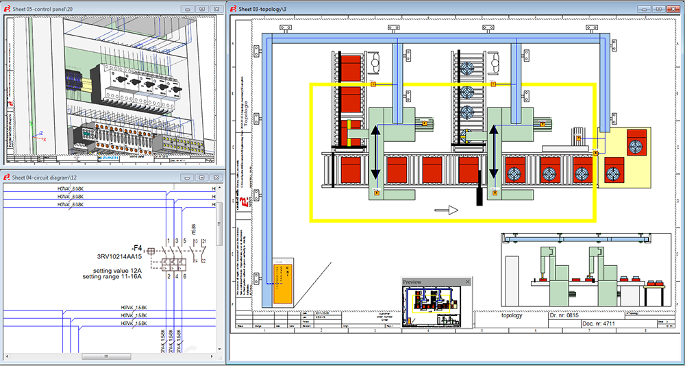
E3.topology is a powerful tool for optimizing the wire harness design process. The tool uses sheets to represent the vehicle chassis or plant layout, to which installation spaces such as dashboards or control panels can be easily added. The connections between these spaces represent wiring harness routes or cable trays. In addition, alternative views of logical devices can be conveniently placed in the relevant spaces within the same project.
As the detailing process progresses, the topology view automatically displays signal logic and wiring information from the schematic, enabling the automatic definition of harnesses or cable trays. Inline devices can be effortlessly added, facilitating the testing of alternate layout configurations. Special reports provide comprehensive information on routes, including cost and weight estimates.
E3.topology seamlessly translates logical designs into the physical world. This tool enables engineers to create electrical topology sheets at any scale and integrate them into the overall E3.series project. It empowers engineers to dynamically create installation spaces for dashboards or control panels, define connection pathways between these spaces, and place components in pre-defined locations.

The benefits of adopting wire harness tools
Early optimization helps minimize design flaws, reduces costs, and saves valuable time during the product development cycle. It enables manufacturers to deliver high-quality wire harnesses that meet customer requirements and excel in competitive markets. By adopting a proactive approach and prioritizing early optimization, engineers can ensure optimal functionality and maximize the potential of wire harness designs.
Tools like E3.topology provide engineers with the ability to visualize and modify wire harness layouts for the entire vehicle or machine, even before 3D routes or physical layouts are available. Capabilities like automatic calculation of segment diameter, weight, and cost, as well as automatic routing of signals, wires, and cables between spaces, significantly reduces errors, lowers costs, and ensures a right-first-time approach.


