Although the engineering process continues to be increasingly connected with digital information flowing along a digital toolchain, there often remains a “disconnect” between the MCAD world and ECAD world that can be challenging if not problematic. Mechanical engineers commonly have no visibility of the wiring harness design and its details. In the same way, electrical engineers must rely on point-to-point measurements from the mechanical world.
Some companies therefore still resort to mechanical prototype assemblies to determine the wiring harness routes, diameters, and lengths. Although this will create correct wire routing information, the time lost waiting for the prototype to be available can be dramatic: It is common to have a 16-week lead time for wiring harness production that delays machine builds, testing, etc.
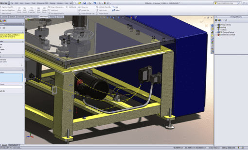
Zuken’s E3.series design platform eliminates these time sinks by combining industry-leading electrical design tools with collaboration capabilities that enable continuous information exchange with the MCAD world. Using the E3.3DRoutingBridge, schematic and connection information from E3.series can be interfaced with all major MCAD systems to allow concurrent mechanical and electrical design.
Wire harness design – a 3D MCAD job or an ECAD competence?
However, there is no generally accepted and preferred design flow between electrical and mechanical engineering: Some companies prefer the physical harness design to be done in the mechanical department, while others prefer the detailed harness layout to be done in the ECAD domain. Of course, the harness must be represented in the 3D MCAD model. Still, it is to all intents and purposes an electrical component that has a very close connection to the schematic design.
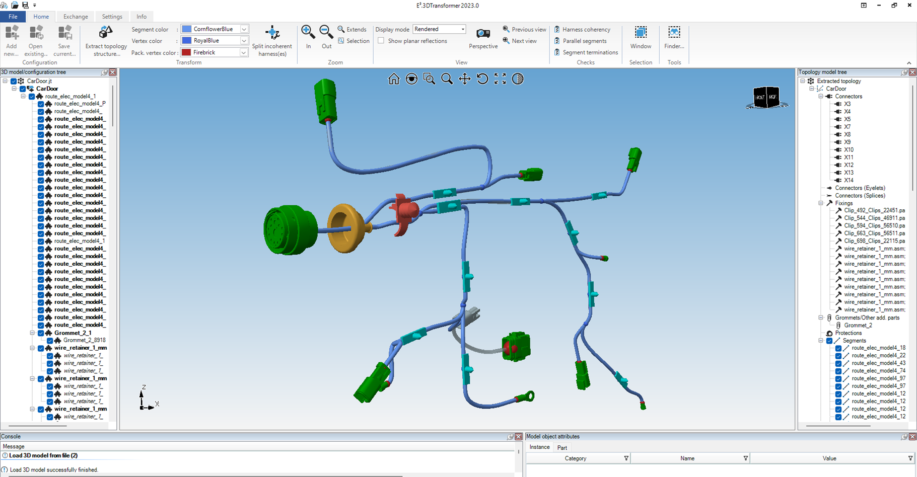
Of course, it is important to use all relevant mechanical definitions of the harness with all details such as topological meshing or bundle lengths for the electrical design. For this challenging task, the Zuken provides an answer to resolving such MCAD integration challenges with E3.3DTransformer: it is able to read native 3D data of the leading MCAD systems as well as industry-standard formats like JT and, using a rule-based extraction engine, it transforms the geometrical harness design into an electro-mechanical topology data model with all relevant objects.
Fixing inconsistencies in MCAD harness representations
In addition, E3.3DTransformer has superior capabilities for finding and healing inconsistencies in 3D MCAD designs so that work can proceed in ECAD without delay, while the MCAD source data is corrected. The resulting electro-mechanical topology data model is then flattened and imported into an E3.formboard harness drawing, which can be completed with comprehensive dimensioning information using the rich functionality of E3.formboard. There is no need to explain that there is also an update process that allows synchronizing the finalized harness drawing with an MCAD representation, updating changes like changed bundle length or added/deleted bundles.
With the combined capabilities of E3.3DRoutingBridge and E3.3DTransformer, Zuken’s E3.series platform supports all kinds of methodologies adopted in the industry. Whatever the customer’s preferred approach may be: the result is always a consistent reduction of engineers’ time and costs.

Learn how to implement an effective ECAD MCAD collaboration for a smooth design flow from start to finish in our on-demand webinar:

- Products
Integrate E3.series with leading MCAD providers through the use of E3.3DTransformer. Integrates with: Dassault CATIA / SolidWorks, Siemens NX, SolidEdge, PTC Creo and Autodesk Inventor to convert 3D harness designs into detailed 2D formboards for manufacturing-ready documentation in E3.series

- Products
E3.3DRouting Bridge - Streamline ECAD-MCAD collaboration by synchronizing connectivity data between E3.series and leading MCAD platforms in real-time.


