For more than 30 years, 3D has been regarded as the state of the art in mechanical design – and for good reason: the representation of a design in three dimensions facilitates the design of surfaces and improves usage of available space by aligning the model more easily with its geometric environment; it is easier to understand and can therefore serve as a common reference between different departments; and finally, the model can serve directly as a starting point for subsequent manufacturing processes such as CNC machining, sheet metal working or mold making and, more recently, 3D printing.
In electronic and electrical engineering, things are still somewhat different: although the third dimension has already made inroads here too, 2D still holds a firm place here and there are good reasons for it: The most important is that in electronic and electrical engineering, the logical diagram continues to provide the basis for the entire design – and a logical diagram is by definition neither scaled nor 3-dimensional, because (as the name suggests) it only describes the logical relationships and not the physical design of a system.
Bridging Logic and Physical Design in Electrical Engineering
This physical layout is reserved for a separate step. In the case of electronic engineering, the task is to connect components with an ever-increasing number of connectors to a printed circuit board by means of copper traces, whilst taking into account complex electrical, physical and production-related rules and constraints, in such a way that both a trouble-free production and a flawless electrical function are guaranteed. And this is where – at least in the latest generation of CAD systems – 3D representations come into play.
In electrical engineering – i.e. in the design of switchgear for mechanical engineering and cable harnesses in the vehicle sector – space is comparatively less of an issue, although the margins are becoming narrower here too. The primary focus here is on the assignment of stop parts, wire diameters, cable colours and connector assignments to the connections defined in the circuit diagram and therefore it is still predominantly a 2D task.
Addressing Tight Installation Spaces with 3D Component Rotation
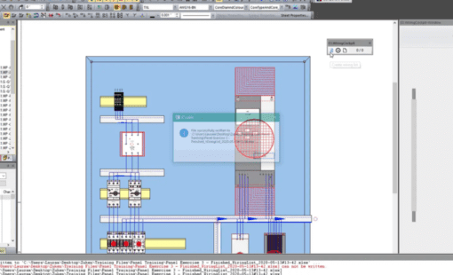
The third dimension only comes into play once the cables, connectors and assemblies defined in the wiring diagram are laid out physically in a control cabinet, a control panel or a wiring harness – depending on the area of application. Again, the main focus is on a clear and unambiguous logical assignment of the elements defined in the schematic design. Even though the representation and collision check in the 3rd dimension is important here too, a superimposition of the original 2D representation in the third dimension in what is called a 2.5D is more than sufficient to achieve the desired result. This enables users to rotate and inspect the 3D representation of a cabinet layout in any desired angle.
The method only becomes somewhat problematic if elements within the enclosure are to be arranged at angles other than in orthogonal directions. For example, when mounting plates are to be arranged not on the same level, but at an angle to each other – or if a terminal strip needs to be fitted in an enclosure at an inclined angle, or if the cover and operating elements of a control panel are to be arranged at an angle.
Advancing Control Cabinet Design with E3.panel
Until now, electrical planners have made do by arranging the relevant elements “flat” in the enclosure, i.e. without an inclination angle, specifying defined excess lengths for the cables, and leaving any reworking of cable ducts to the production department. It can be done in this way and it is a perfectly viable approach – but it certainly isn’t elegant.
For this reason, E3.panel, the E3.series application for control cabinet assembly, has been expanded in version 2023 to include a new function that makes such “workarounds” a thing of the past: Objects in the control cabinet can be tilted at any angle in all axes. This extension of the 3D functionality in the control cabinet layout was primarily designed to address the increasingly tight installation spaces for control cabinets.
