CR-8000 Design Gateway
Menu
- Blog
October 07, 2021
Automatic Block Update: Automatically generate FPGA pin assignments in Design Gateway designs
Zuken's Custom Development Group has developed a solution that enables simultaneous IC, connector, and PCB development by automating the updating of pin assignments in PCB design.
Read now
- Blog
March 16, 2021
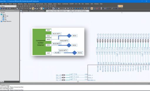
Tech Tip: Creating and Verifying a System Circuit Diagram for Multi-Board Design in CR-8000
In part 1 of this series, I introduced the different methods for multi-board design in CR-8000. In most cases, the design starts with a system circuit diagram. Today you'll learn how to create and verify one in CR-8000.
Read now
- Blog
May 12, 2020
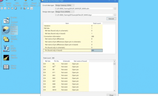
Tech-Tip: Design Synchronization Tool
When your design is nearing completion and you want to make sure the schematic matches what you have in your board try using the Design Gateway, Design Synchronization Tool.
Read now
- Blog
November 05, 2019
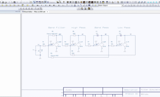
Tech Tip: How to Simulate Analog Circuit Design in Design Gateway
This video shows how users can simulate and analyze Analog circuit design in the CR-8000 Design Gateway interface with the PSPICE simulation tool.
Read now
- Blog
August 06, 2019
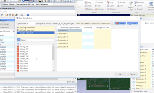
Tech Tip: Setting Clearance Classes in CR-8000 Design Gateway
When a design requires specific minimum spacing between net classes, these clearance classes can easily be created and assigned in CR-8000 Design Gateway.
Read now
- Blog
February 19, 2019
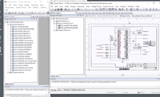
Tech Tip: Re-use Block Basics – Using Design Gateway to build a circuit block library
And it's easier than you think. A reuse library can boost productivity and product reliability. Read and watch our video to learn more.
Read now

- Blog
December 04, 2018
Tech Tip: How to Import DXF Data into CR-8000 Design Gateway Symbol Editor
Follow along with this step-by-step video and learn how to import DXF data into the CR-8000 Design Gateway symbol editor.
Read now
- Blog
September 25, 2018
Tech Tip: CR-8000 Design Gateway 2018 Function for Adding Multiple New Sheets Collectively
There’s a greatly improved option in CR-8000 Design Gateway 2018 that gives users the opportunity to add multiple sheets when creating new designs or when adding sheets to an existing design.
Read now
There's a greatly improved option in CR-8000 Design Gateway 2018 that gives users the opportunity to add multiple sheets when creating new designs...

- Blog
July 03, 2018
Tech Tip: CR-8000 Design Gateway 2018 Execute Macro to Multiple Sheets
There’s an exciting new option in CR-8000 Design Gateway 2018: “Execute Macro to Multiple Sheets. The new functionality allows you to execute macros on specified sheets all at once.
Read now
There's an exciting new option in CR-8000 Design Gateway 2018: "Execute Macro to Multiple Sheets. The new functionality allows you to execute macr...
- Blog
May 15, 2018
Tech Tip: Auto-hide Panels in CR-8000 Design Gateway
Oftentimes when we’re working on schematics, the panel menus take up a ton of space on the screen. This is where the Design Gateway auto-hide feature comes in handy.
Read now
Oftentimes when we're working on schematics, the panel menus take up a ton of space on the screen. This is where the Design Gateway auto-hide feat...

- Blog
March 01, 2018
Lower Manufacturing Costs with XJTAG’s New Design Gateway Plugin
XJTAG has partnered with Zuken create a new plugin for Design Gateway and is offering it free of charge. The plugin, called XJTAG DFT Assistant, helps to validate correct JTAG chain connectivity, while displaying boundary scan access and coverage onto the schematic diagram through full integration with Design Gateway.
Read now
XJTAG has partnered with Zuken create a new plugin for Design Gateway and is offering it free of charge. The plugin, called XJTAG DFT Assistant, h...

- Blog
July 14, 2017
Renishaw Designs Flex PCBs in True 3D with MCAD Integration using Zuken's CR-8000
The PCB design team at Renishaw work with flex PCBs and flexi-rigid boards that require detailed signal integrity analysis. To achieve the most accurate results they are working with Zuken’s electronic PCB design software to visualize boards in 3D using imported MCAD data. This also ensures that sure high-speed digital signals can be transmitted with minimal distortion.
Read now
When Renishaw decided to migrate to Zuken’s latest PCB design suite in 2016, a main driver was the suite’s capabilities for designing and anal...