High-speed PCB Design

- Blog
- Blog
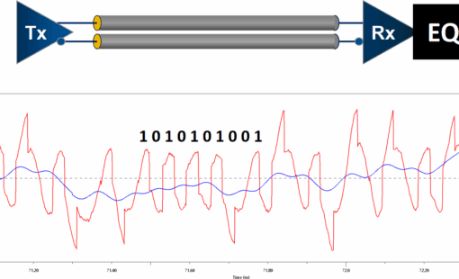
Learn the two key fundamentals for reliable high-speed serial link design and how to overcome signal integrity challenges at multi-Gbps speeds.
- Blog
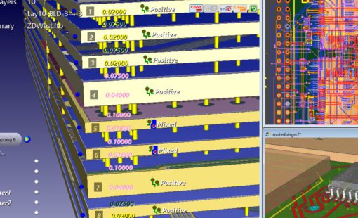
Discover how CR-8000 and Polar Speedstack™ enhance high-speed PCB stack-up design by optimizing impedance control and manufacturability for improved performance.
- Blog
Although memory technology continues to evolve, in the current technology landscape, DDR4 is often a critical hurdle in the design process of an electronic application because of the large number of rules and constraints which have to be obeyed for the implementation of high-performance memory subsystems. Learn what to consider.
- Blog
Printed Circuit Board design has been at the core of electronic innovation for decades. However, as technology continues to advance, PCB design faces new challenges that make it increasingly complex and demanding.

- Blog
Zuken is taking its Simulation and Analysis Performance to the next level by introducing a new processing technology to its PI/EMI analysis tool. Multi-threading will speed up PI analysis which will give PCB designers a boost in productivity, especially when evaluating different design alternatives for PDN structures.
- Blog
A trend towards low power design prevails in the electronics industry today and is not likely to change in the near future. This development is driven by many reasons but primarily by the performance and storage density demands of mobile devices, where a reduction of the power consumption is crucial to extending battery life without sacrificing the bandwidth. This comprehensive guide helps you mitigate LPDDR4 Design.
- Blog
PDN impedance is becoming more and more of a headache for PCB designers as IC vendors are defining increasingly tight so-called ‘target impedance limits’. This article explains what PDN impedance means for PCB designers and what to pay particular attention to.

- Blog
Double Data Rate 5 (DDR5) is the next-generation standard for random-access memory (RAM). The new specification promises to bring chips that have much higher performance than the existing DDR4 modules, as well as lower power consumption. Let us show you how you can be first to market with DDR5!

- Blog
To keep a good high-speed signal quality from driver to receiver on a PCB is not an easy task for designers. One of the most challenging issues is managing the propagation delay and relative time delay mismatches. Let me take you through the process...

- Blog
What IC designers do to help us route high-speed PCBs

- Blog
PCB designers typically have little or no experience with SPICE applications. No worries, follow along with me and get to know your SPICEs!

- Blog
In part 1 of this blog we took a back-to-basics approach and discussed line impedance and its effects in signal integrity. As every electrical conductor comprises capacitance, an inductance, and a frequency-dependent ohmic resistance, and with increasing frequencies, these electrical characteristics will influence and distort the signal.

- Blog
Impedance and impedance control are some of the oldest and most discussed topics in PCB design. They are especially important in high-speed design related to signal integrity. In this, the first of a two-part blog, we’ll go back to the basics of impedance/impedance control and consider what influences line impedance. In part two, we’ll set about controlling it.

- Blog
It’s not often you spend your work day laughing AND learning. But that’s how it went for Zuken Europe’s first foray into filming videos with our customers.
- Blog
We’re happy to announce that Speedstack, Polar Instruments’ layer stackup design/documentation tools, can now be directly linked to Zuken’s CR-8000 Design Force and DFM Center.