Multi-board designs are becoming increasingly important as today’s products require higher speeds and more complex circuits in smaller dimensions. These products contain multiple, interconnected circuit boards.
Combining the individual boards in the housing and ensuring that they are properly connected is a challenging task in the product development process. There is more than one way to create multi-board layouts in CR-8000.
1. Physical Connectors
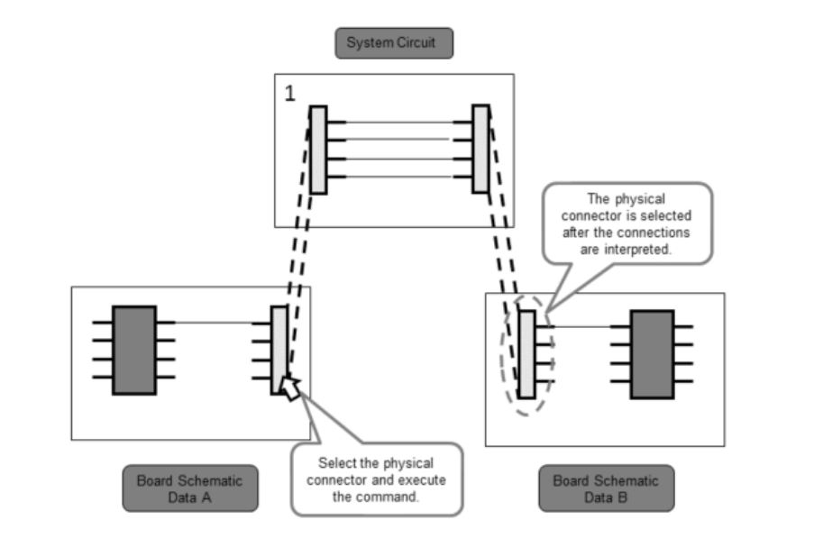
The first – and probably the most common – approach with the following situation: There are individual circuit diagrams containing physical connectors and these can now be used to link various individual designs.
First of all, a system circuit is needed, with which these physical connectors can then be interlinked. There is hardly any need to change the design flow for this. You can simply use existing designs, define the physical connectors and create a system circuit in parallel with the existing designs.
2. Temporary Parts
The second option also uses circuit diagrams for linking. This time, however, not on the basis of physical connectors, but via so-called temporary components in the schematic.
Simply place a schematic symbol defining the connection points between the schematics, and during forward annotation, you can then assign a temporary footprint to that symbol. This way, you can connect individual PCBs to each other.
3. Padstacks
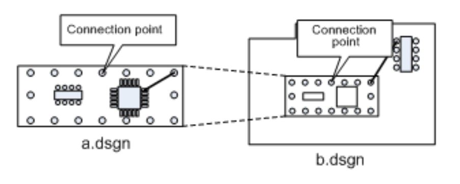
The third possibility would be to create a connection without any schematic at all. To do so, you define a temporary footprint in the layout using connection points, also known as pad stacks. You place these at the desired location and then use these connection points to connect your PCB designs in the layout.
In the next Tech Tip of this multi-board design series, I will explain how to create and validate a system circuit diagram in CR-8000.
You can find more PCB design tips explained in detail and practice-oriented in our on-demand webinar library.
Also see:
- Blog
The benefits of developing all boards of a system concurrently on a single CAD canvas. Stacking PCBs, as opposed to connecting with cables, in multi-board design is a current and highly popular trend, as manufacturing costs are reduced and reliability improved.
- Webinar
- Products
CR-8000 Design Gateway provides a platform for logical circuit design and verification of multi-board system-level electronic designs.

- Products
CR-8000 is a System-Level PCB & IC Package Design software including 3D Multi-board, Analysis and MCAD Integration
