Understanding Electrical Wiring Diagrams: Four Primary Types You Should Know
Menu
Electrical wiring diagrams are essential documents in the field of electrical engineering. They provide a visual representation of the electrical system, making it easier to plan, install, troubleshoot, and maintain electrical circuits. There are several types of electrical wiring diagrams, each serving a specific purpose.
Schematic Diagrams
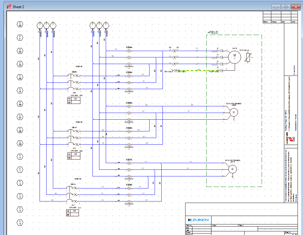
Schematic diagrams show the connections and functional items of an electrical circuit, but not the physical layout of the wires. Schematic diagrams use standardized symbols to represent different electrical components, like resistors, capacitors, inductors, switches, and power sources. They are used both in designing and troubleshooting electrical circuits, such as those in appliances, industrial machinery, or electronic devices.
In the DIN Standard, the signal paths in an electrical schematic are displayed as straight horizontal and vertical lines that are organized from left to right and then from top to bottom. If the signal flow is organized from top to bottom first and then from left to right (ANSI/IEEE), the schematic is also referred to as a “ladder diagram”. Ladder diagrams are typically used in North America.
A simplified and less technical type of schematic diagrams are pictorial diagrams. These diagrams use pictures of components rather than abstract symbols and are therefore easier to understand for those who are not familiar with electrical symbols. They show the relative position of the components and are often used in instructional materials.
Electrical Schematic Design Software
Wiring Diagrams
Unlike schematic diagrams, wiring diagrams show the physical connections and layout of an electrical system or circuit. They display how the wires are connected and located in the actual device. They include information on wire colors, sizes, splices, and insulating materials, as well as the physical connectors between all the components.
Examples of Electrical Wiring Diagrams
Electrical wiring diagrams are essential tools in the field of electrical engineering and electrician work. They provide a visual representation of the electrical system, making it easier to install, troubleshoot, and maintain electrical circuits. There are several types of electrical wiring diagrams, each serving a specific purpose (see below).
Wiring Diagram Formats
Wiring diagrams that show the physical connections of a circuit typically come in several standard formats, each tailored to convey specific types of information effectively. Here are some of the standard formats:
- Single-Line Diagrams (SLDs) Single-line diagrams use a single line and standard symbols to represent the path of electrical circuits. Single-line diagrams provide a simplified view, showing the main connections and branches of the circuit rather than all the actual wires. SLDs are especially useful for depicting complex electrical distribution systems, such as those found in buildings or power plants in the initial stages of circuit design.
-
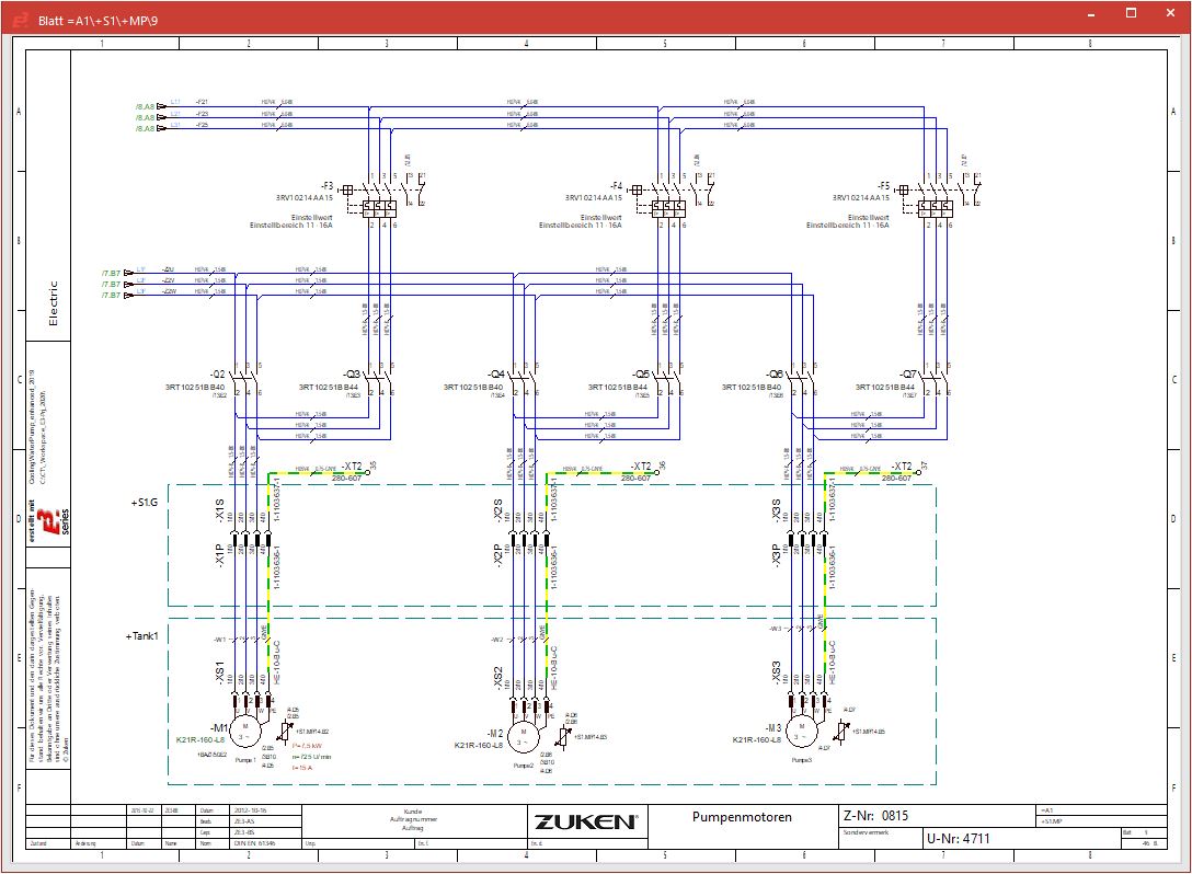
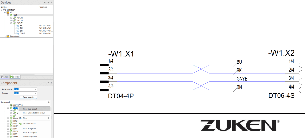
Multiline Diagrams
Unlike single-line diagrams, which use a single line to represent multiple conductors or electrical paths, multiline diagrams depict each conductor separately. This includes detailed information about connections, wire sizes, colors, and types. They are used when detailed information about the physical wiring is necessary, such as during the installation, troubleshooting, or maintenance of electrical systems. -
Block Diagrams
Block diagrams are used to show the basic functions of an electrical system and how its components are connected. They use blocks to represent components and lines to represent connections between them, giving a high-level overview without going into details of wiring or physical placement. Block diagrams are typically used in the early stages of design to outline system functionality and interconnections.
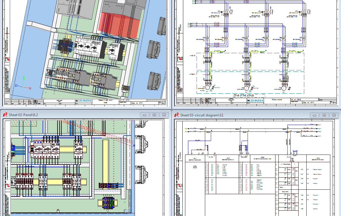
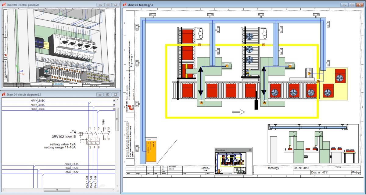
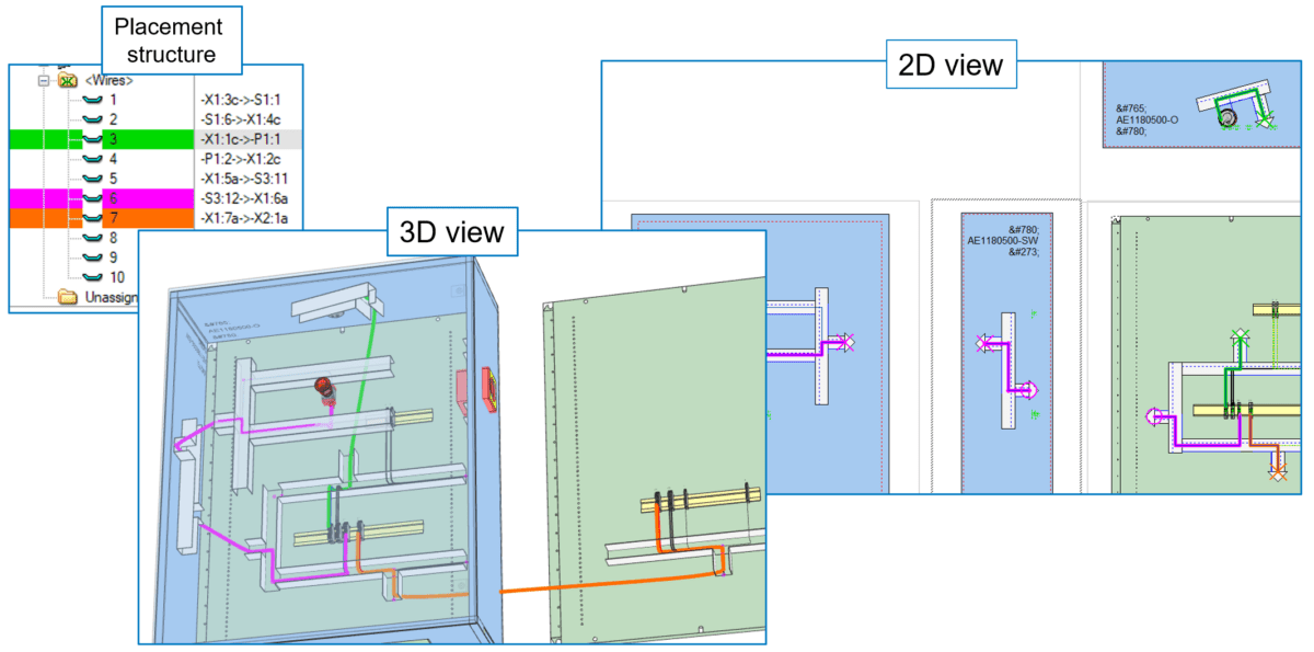
Panel Diagrams
Panel diagrams show the layout of components within a physical enclosure like an electrical panel or control box, typically in a mix of 2D and 3D representations, also referred to as 2.5D. Panel diagrams include details about the physical arrangement of components, wiring connections, and the physical pathways for conductors. Panel diagrams are essential for the installation, maintenance, and troubleshooting of control panels in industrial, commercial, as well as residential settings.
Electrical Panel Design Software
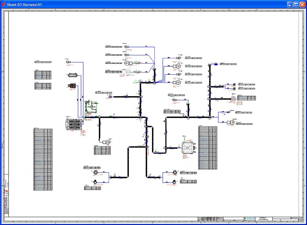
Formboard Diagrams
A formboard design or diagram is a full-scale diagram that illustrates the layout and routing of wiring harnesses in complex systems. A formboard diagram is typically printed at a 1:1 scale to create and assemble bundles of wires or cables that transmit electrical power or signals in aircraft, automobiles, spacecraft, and large industrial machines. Technicians use formboard diagrams as guides to cut, layout, and assemble the wires and components into a harness. The life-size nature of the diagram allows wires to be laid directly over it, ensuring accurate length and placement.
Formboard Layout Software
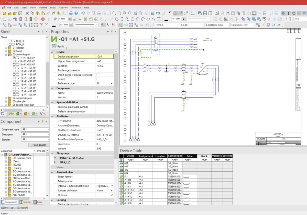
E3.series from Zuken – an All-Encompassing Solution for Sophisticated Wiring Designs
E3.series provides a leading single-platform solution to take electrical and fluid control designs from concept to manufacture. E3.series encompasses schematics design, wiring design as well as fluid diagrams, through to applications for control cabinet and wire harness layout in 2D and 3D in one single integrated, but modular configurable environment.
E3.series offers an all-encompassing solution for crafting sophisticated wiring diagrams. Professionals around the globe trust E3.schematic because it streamlines the design process while ensuring precision and efficiency.
Conclusion About Wiring Diagrams
Whether you are studying electrical engineering, working as a professional technician, or nurturing an electrical curiosity, distinguishing these four wiring diagram types can sharpen your insight into electrical systems. Each type has its distinct function, with the most suitable often hinging on the particular task. It is essential to use a computer-aided design tool that provides the ability to switch between the different representations in a seamless way.
Discover E3.series, Electrical Design Software from Zuken
Tune-in to our expert-led video series, where we explore best practices and strategic insights to help you navigate projects with greater precision and efficiency using E3.series.
Start with our first session: How to Setup an E3.series Project and build a solid foundation for optimizing your workflow.
Watch Episode 1

Klaus Wiedemann is responsible for marketing across Europe, including web content, public relations, and marketing programs. He works closely with product management, technical experts, and customers to align and communicate Zuken’s product solutions with market needs. Klaus is passionate about language and its correct usage, and he also enjoys tinkering with mechanical contraptions such as run-down bicycles and motorbikes.

- Case Study
November 22, 2018
Kässbohrer Transport Technik
The Austrian manufacturer of vehicle Transporters, Kässbohrer Transport Technik, achieved a substantial improvement in process reliability in the generation of individualized assembly instructions and schematic documentation by implementing E3.series. Turnaround cycles for special projects were reduced by 60 to 90%.
Read now
achieves 60-90% reduction in electrical documentation turnaround for customer specific vehicle configurations
- Case Study
November 22, 2018
Kellenberger
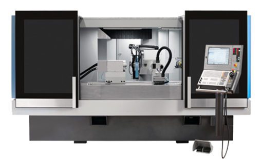
Kellenberger develops and produces numerically-controlled precision grinding machines and systems for sectors such as automotive, medical devices and industrial machinery. The Swiss-based manufacturer recently introduced Zuken’s E3.series to automate the generation of schematics for customer-specific machine configurations, cutting the time taken by more than 90%.
Read now
~90% time saving to generate customer-specific
schematics by implementing options and
variants in E³.series.
- Case Study
November 15, 2018
Müller Martini
Müller Martini supplies highly flexible, customized print processing machines to the graphics industry. The Swiss-based company recently took the replacement of an end-of-life CAD installation as an opportunity to re-engineer established procedures in electrical engineering and handover to production.
Read now
enhances variant and option handling and reduces manufacturing costs by moving to an object-oriented ECAD environment.

- Case Study
October 10, 2018
Krone
KRONE, a major brand in the agricultural machinery market, implemented an interdisciplinary product development process. Using Zuken’s E3.series, KRONE linked ECAD, MCAD and ERP to develop an integrated digital engineering and sourcing process, achieving sizable benefits for both sourcing and service. With an integral representation of mechanical and electrical product information, KRONE was able to make solid progress in implementing its major business optimization strategies: Industry 4.0 and Farming 4.0.
Read now
Krone Agricultural Machinery integrates ECAD, MCAD and ERP to enable integrated design and sourcing
Related Products and Resources

- Products
October 04, 2022
Electrical Design Automation
Zuken E3.series provides a wide range of tools to enable electrical design automation. Reducing the design workload and enabling faster electrical design process.
Read now
E3.series Electrical Design Automation

- Software Evaluation
June 28, 2021
Electrical / Fluid Design Software Evaluation: E3.series
E3.series Test-Drive provides a web-based training course that guides you through the creation of a real life design example with E3.series using E3.cable and E3.panel
Register Now
E3.series Test-Drive. One Registration, Two Evaluations - Cable/Wire Harness Design and Machinery/Panel Design