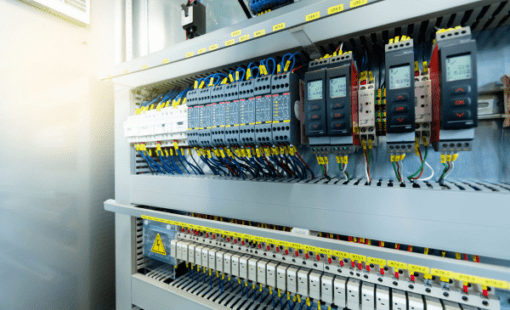
In today’s world, almost all devices and equipment are operated by electricity or run with a significant involvement of electrical devices and controls. To plan these electrical devices, systems and their associated controls, engineers use CAD systems – just as they have done for a long time in mechanical engineering. The term that has become more or less established for these is Electrical Computer Aided Design or ECAD/electrical CAD for short. In other words, ECAD refers to the planning and design of electrical machines and systems the domain of high-current technology.
High-Current Technology vs Low-Current Technology
A distinction must be made between high-current technology and components and assemblies that are operated with low currents, which essentially means printed circuit boards and the microchips installed on them. These applications have very specific requirements and consequently also require software systems that have been specifically designed for this area of application. Typically, these systems are classified under the collective term EDA (for Electronic Design Automation) with the subcategories of PCB CAD and IC design. These systems shall not be considered in today’s discussion and will be reserved for another occasion.
What is an ECAD System?
Electrical CAD systems facilitate the design of electrically operated and controlled machines and systems in the field of power electrics. The most important areas of electrical power technology are 1) electrical energy technology, 2) electrical drive technology and 3) electrical automation technology.
In some cases, the functional scope of electrical CAD systems includes the planning of hydraulic and pneumatic systems that are controlled with electrical impulses and therefore require an integral planning that combines both views.
What Data Does an ECAD System Produce?
Essentially, electrical CAD systems are used to create all the data and documents required in the course of a development process. In detail, these include
- Circuit diagrams – abstract graphical representations of the logical structure of a circuit using standardized symbols (DIN EN 60617 for Europe and ANSI/IEEE Std 91a-1991 for North America)
- Cable diagrams – logical representations of a circuit, extended by physical attributes (cables, cable bundles, plug connections, terminal assignment)
- Control cabinet layouts – three-dimensional arrangement of the electrical equipment defined in the cable diagram (wires, terminals, switching elements) within an enclosure
- Manufacturing documentation – for cable harnesses containing details for bundling, taping, fastening, wiring and connector assignment
- Parts lists – for the procurement and provision of all components required for production
- Data files – for automated production from mechanical machining of enclosures to outputs for automatic cable assembly
- Reports – visualization of specific data in a spreadsheet representation, ideally with a direct reference to the corresponding items in a drawing
- Assembly instructions – detailed information required to accurately and safely assemble, wire, and test the cabinet, including bill of materials (BOM); wiring diagrams; assembly, wiring and labeling instructions; testing procedures and quality control checklists
- Service documentation – start-up procedures, maintenance guidelines, troubleshooting guides, schematic and wiring diagrams, safety information, parts list and spare parts catalog
Requirements for a State-of-the-Art ECAD System
A modern, up-to-date CAD system for electrical engineering maps all these planning steps, including fluid engineering, in a consistent, ideally modular, configurable solution that ensures that all planning steps are seamlessly interlinked and connected in order to eliminate data discontinuity, duplicate data acquisition and the associated error risks.
One example of such a modular, end-to-end system is E3.series from Zuken: a professional, intuitive solution that covers both the logical and physical layout of electrical, hydraulic and pneumatic control systems. E3.series covers the entire engineering process, from circuit diagrams and cable diagrams to the layout of control panels and cable harnesses, including the generation of outputs for production, assembly and service. The object-oriented system architecture of E3.series enables a permanent synchronization of all engineering stages on the basis of a central database that contains all the information required for engineering, ordering and production.
E3.series – Electrical Design Software
Key Considerations in Electrical Design Software Selection
A prerequisite for the full utilization of a system whose capabilities go beyond simple drawing is a complete description of all components used in a design within a system database that can be accessed by all applications employed. It is important to note that some vendors advertise their own data portals with hundreds of thousands of components and more. On closer inspection, however, the quality of these data portals should be viewed with some caution, as the component data they contain is often incomplete, incorrectly organized or simply out of date.
A sensible alternative is therefore the use of neutral data portals such as Cadenas Component Cloud, which are supplied with up-to-date data by the component manufacturers themselves and also offer the option of requesting data directly from the manufacturer or having it provided by specialized service providers at short notice.
Customization Challenges in Electrical Design for Manufacturing
In addition to the consistency and integration of all engineering stages, there are further aspects that are particularly important for single-item and variant manufacturers – as is typical in the machinery and manufacturing industry:
The first aspect concerns the fact that machines and systems are usually supplied in customer-specific configurations. To avoid creating the entire electrical documentation from scratch, it should be possible to define and store various configurations in an over-defined (“150%”) project from which they can be retrieved by means of a filter.
The second aspect relates to the reuse of design elements across different projects, with the aim of reducing the overhead for individual design and increasing development productivity. The ability to organize projects using so-called hierarchical blocks, which only show the connections to the immediate environment in the form of “black boxes”, is better than simple copy & paste. The content of the “black box” is referenced on a separate sheet in which all details are displayed in full. In this way, it can simply be loaded from a library.
Traceability – The Key to Successful Reuse of Designs
The prerequisite for the successful use of options, variants and hierarchical blocks in practice, is the ability to fully trace and document the utilization of these configurations and blocks in different designs in order to be able to carry out any necessary updates across all instances. For E3.series, Zuken offers a powerful solution for this with DS-E3, which can read and analyze projects in their original format. This option is not available when storing data in a standard PDM system.
Further information on these and other aspects can be found at Zuken’s Electrical Design Software – E3.series.

- Products
The Zuken Component Cloud for E3.series provides online access to free, validated, high-quality electrical component data to users of Zuken’s E3.series electrical design tools.

- Products

- Products
E3.series is a true concurrent electrical engineering environment supporting advanced requirements for electrical documentation, cabinet and wire harness design and manufacturing outputs.


