PCB-level EMI and power supply system analysis
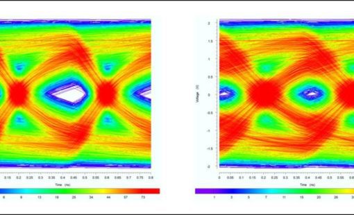
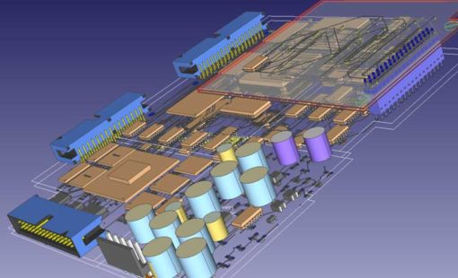
Design Force PI/EMI Advance provides powerful capabilities for PCB-level EMI and Power Supply System Analysis. It offers a fast estimation of worst-case electromagnetic emissions, taking into account the PCB, attached cables, and heatsinks, covering both Common-Mode and Differential Mode emissions.

PCB-level EMI and power supply system analysis

Fast estimation of worst-case electromagnetic emissions
DC analysis for detailed assessment of voltage and current distributions
Incorporate our EMI and Power Integrity Analysis tools into your electronics engineering workflow and equip yourself with the insights needed to optimize your designs for reliability and compliance.
Our EMI analysis tool offers a comprehensive examination of your electronic system, identifying major EMI sources efficiently and rapidly.
Evaluate both common mode and differential mode emissions to gain insights into signal propagation throughout the system.
Visualize areas where I/O crosstalk occurs, enabling precise pinpointing of potential interference zones.
Consider various external antenna mechanisms that might impact your system’s EMI, ensuring a holistic approach to interference management.
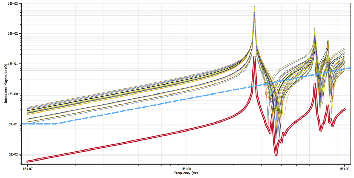
Our tool provides wideband Power Integrity Analysis of supply systems up to 10 GHz, uncovering high AC-impedance regions and potential resonances’ root causes. Avoiding high resonance peaks will improve the EMC behaviour also.
Evaluate the efficiency of decoupling capacitors (Decaps) and visualize the impact of mounting inductances. Understand the performance of your Decaps (placement, connection inductance or wrong values of the decaps)
Define virtual Decaps and place them virtually on your board for what-if scenarios, optimizing decoupling strategies and ensuring readiness for unforeseen challenges.
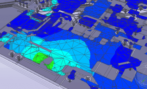
Perform DC-Analysis to identify IR-drop situations and regions with a high current load, providing insights into the power delivery system performance.
Identify areas where IC power pins receive insufficient supply voltages, preventing potential performance issues.
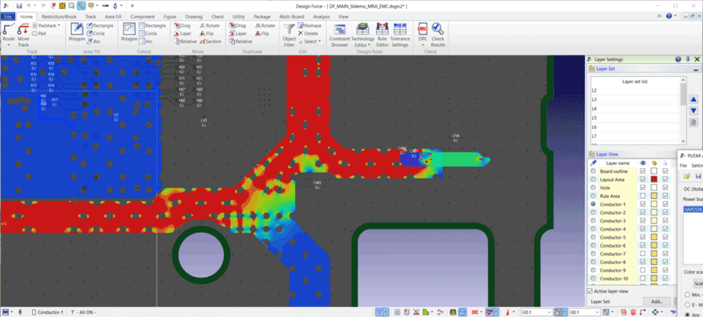
Extract DC-resistances between power pins to assess the efficiency of your power delivery network and allows to check IC vendor requirements for the connection from source to the sinks
Explore what-if scenarios by driving the supply system with alternative voltage sources, making your design adaptable to changing conditions.
Recognize stressed vias under high DC-current loads, ensuring the reliability of your power delivery network. Cross-probing into the CR-8000 design canvas allows a straight-forward identification of problematic vias facing the risk of fusing.
Related Resources
Using the example of the analysis of SerDes transmission paths such as PCI Express, SATA or USB3, we explain the methodology of an analysis- and constraint-driven assembly development with CR-8000 Design Force.
In this presentation you will be introduced to the necessary steps in constraining and validation of LPDDR4 on the basis of a real design realized in CR-8000 Design Force right first time.
CR-8000 advances system-level PCB design with significant enhancements in analog simulation, SI analysis, and intelligent layout and routing
In our webinar we will provide an introduction to the challenges of signal integrity and the underlying physical effects. This will provide the basis for practical tips to address the related challenges during PCB design.
ONTEC faced a difficult challenge: develop a multimedia broadcasting product while complying with a customer’s electromagnetic interference requirements, all within a tight development schedule. ONTEC used Zuken’s CR-8000 with Keysight’s ADS (including SiPro) to meet the requirements of the challenge
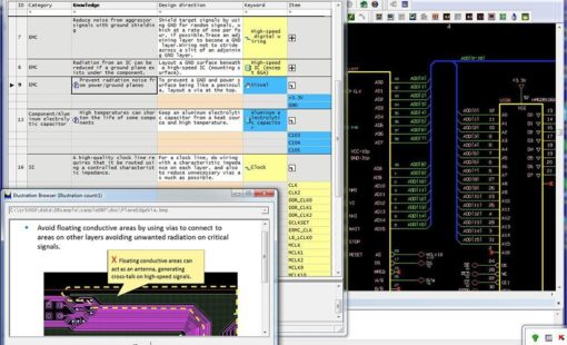
In this presentation, an EMC minded PCB design approach is presented, allowing designers to understand which EMC rules will apply to PCB projects and how EMC analysis capabilities can be utilized in the CAD flow to reduce the risk of EMC compliance failure once the board is manufactured.
Related Blog Posts
Double Data Rate 5 (DDR5) is the next-generation standard for random-access memory (RAM). The new specification promises to bring chips that have much higher performance than the existing DDR4 modules, as well as lower power consumption. Let us show you how you can be first to market with DDR5!
To keep a good high-speed signal quality from driver to receiver on a PCB is not an easy task for designers. One of the most challenging issues is managing the propagation delay and relative time delay mismatches. Let me take you through the process...
What IC designers do to help us route high-speed PCBs
In part 1 of this blog we took a back-to-basics approach and discussed line impedance and its effects in signal integrity. As every electrical conductor comprises capacitance, an inductance, and a frequency-dependent ohmic resistance, and with increasing frequencies, these electrical characteristics will influence and distort the signal.
Impedance and impedance control are some of the oldest and most discussed topics in PCB design. They are especially important in high-speed design related to signal integrity. In this, the first of a two-part blog, we’ll go back to the basics of impedance/impedance control and consider what influences line impedance. In part two, we’ll set about controlling it.
Tips for when routing differential pairs - You can tell when something isn’t as clear as it should be. The same questions come up time and again. You ask three experts and get three different answers. Routing differential pairs can be like that. Why? Because “it depends” - on exactly what signals those pairs are carrying and what kind of PCB you’re creating.
CR-8000 Design Gateway provides a platform for logical circuit design and verification of multi-board system-level electronic designs.
CR-8000 Design Force is the fastest, most effective PCB design solution available today. Design Force enables design teams to layout and verify their designs in the context of a complete system or product.
