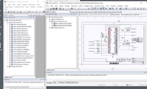
Support for multi-board design and extraction of multiple PCB netlists from one schematic
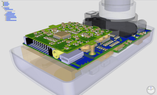
Design Gateway is a platform for logical electronic circuit design and verification of single and multi-board system-level designs. It supports a true system-level PCB design in which individual circuits can be represented and connected as blocks. The platform enables engineers to manage signal continuity (interconnects) at the system level rather than just at the design level, allowing for an evaluation of board-to-board signal continuity.

Support for multi-board design and extraction of multiple PCB netlists from one schematic

Interface with best-in-class simulation tools for analogue/mixed signal, RF, and system level analysis
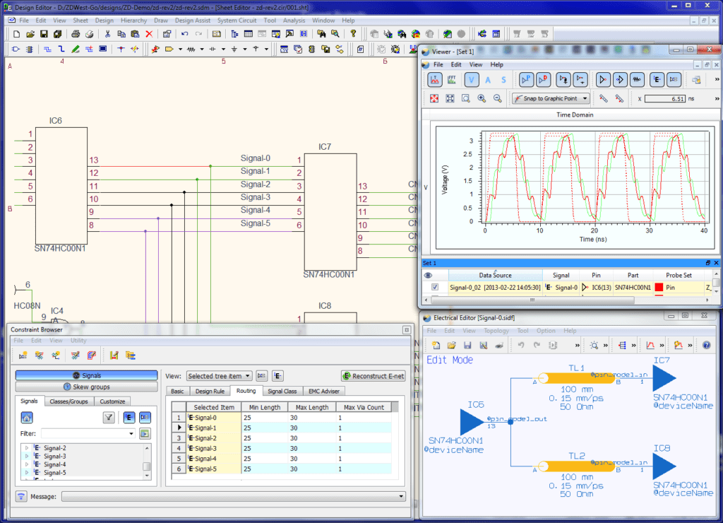
"What-if” studies to determine best termination and topology of critical signals

Parallel use of black box symbols and parts to enable initial layout early in the design process
Design Gateway brings extensive design, simulation, and analysis capabilities to your desktop. It allows companies to manage and make optimal use of engineering design data across all company and team sites. Intelligent multi-board PCB design is inherently supported in Design Gateway.
The platform provides complete system-level PCB design. Native and interactive integration with a wide range of signal integrity (SI), analog, digital, and multi-technology verification tools for electronic circuits is provided. Through this, it also supports the co-simulation of analog and digital functional blocks and programmable devices. Design Gateway enables design re-use, allowing engineers to use proven and tested logical circuits from previous projects.
How to manage signal continuity (interconnects) at the system level in a compact 1:20 min overview
A complete solution for the design and verification of single and multiboard systems
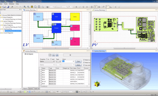
Design Gateway allows you to design a true system-level electronic circuit design by creating a board-level block or connector symbol for each individual circuit, and connecting them together to define a complete system. Engineers can avoid maintaining spreadsheets of system interconnects, and manage them with intelligent graphical design.
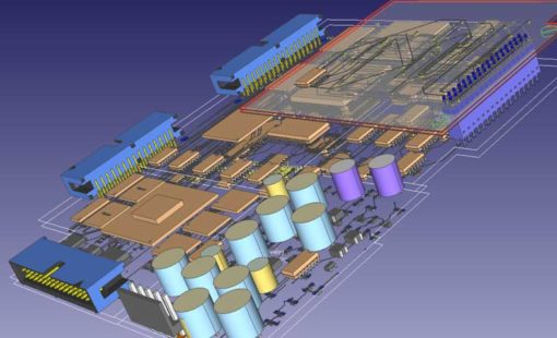
With the power of the multi-board design technology in Design Gateway, you have the option of selecting each board symbol and generating a netlist for each PCB or create a full system-level netlist to support the complete analysis of a product.
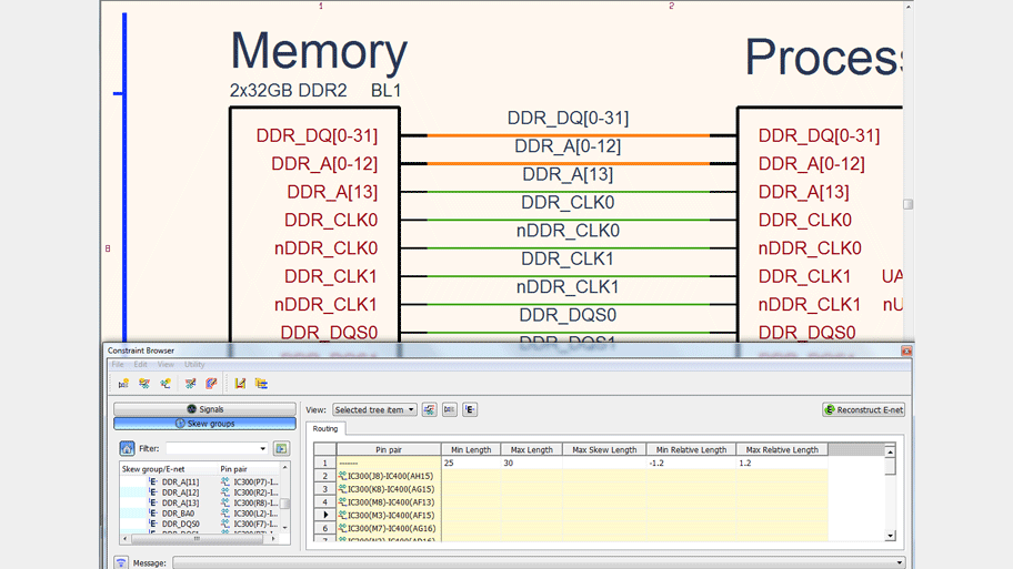
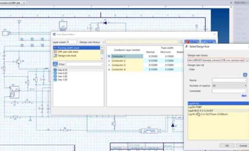
Whether you are challenged with the complex requirements of DDR2/3/4 or faced with incorporating the latest high-speed interfaces, the Constraint Browser within Design Gateway enables you to define constraints for any combination of nets, extended nets, differential pairs, and busses using a spreadsheet approach. In the same instance, a user can continue adding layout rules for nets and manage complex spacing rules within net groups and between net groups.
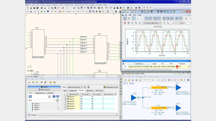
With embedded simulation and verification, and flexibility to interface with best-in-class tools, Design Gateway reduces errors and improves your design cycle time by utilizing the same schematic for both PCB layout and simulation. Whether you require analog or digital simulation, verifying polarized capacitors are connected correctly, or insuring that the simulated signal voltage doesn’t exceed power ratings of a component, you can accomplish all this in a co-design flow using Design Gateway.
The benefits of design reuse are well-known, but implementing a methodology that is flexible, easy to use, and can take advantage of data management was not fully realized until Design Gateway. Design Gateway introduces a flexible approach that allow you to design with certified circuits, use a circuit from an existing design as a template for a new design, or creating a multi-PCB design – using either a top-down or bottom-up approach. Block circuits can be saved in a library for you to catalog and search and add to a design. Revision control can be used to govern any changes to a circuit – all part of Design Gateway’s robust approach to block circuit management.
![]()
Zuken and SiliconExpert have partnered to deliver critical component information to engineers within the CR-8000 and DS-CR design and database environment. The integration enables engineers to make better component selection decisions, resulting in higher quality products and lower costs in less time.
Learn moreThe following can be added to extend the functionality of CR-8000 Design Gateway
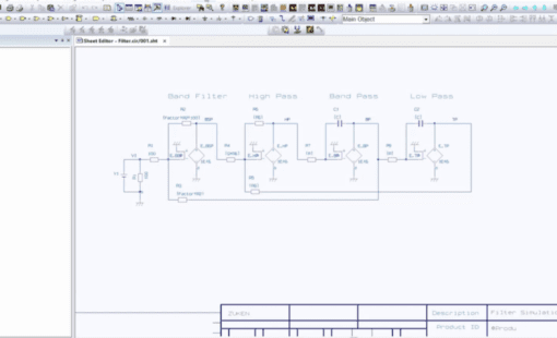
A simulation cockpit for Spice simulation tools (PSpice, LTSpice, HSPICE).
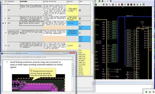
Circuit DR-Navi helps design teams consolidate engineering expertise and best practices into a central knowledge base integrated with the design process. During logical electronic circuit design, engineers can access a standard set of requirements or create project-specific instructions to drive design guidelines across the PCB design flow.
Graphical Pin Manager (GPM), offers an effective FPGA / PCB co-design environment providing support for the latest devices offered by FPGA vendors, such as Xilinx, Altera, Lattice, and Microsemi.
Design Gateway’s Circuit Adviser enables engineers to conduct concurrent, advanced electrical rule checks during logical circuit creation. Users can specify rules and conditions, create check results, cross-probe results with the design and generate summary reports.
Design Gateway Viewer is a native schematic data viewer with comprehensive analysis capabilities, such as cross-probing, constraint viewing, signal classes and many more.
Scenario EX enables to check the electrical characteristics and the connection topology of signal tracks. It allows “What-If Scenarios” of both schematic and layout data to optimize the behaviour of a circuit. It can be used both for interactive design and design verification.
Related Resources
Find out more via our webinars, blogs, press releases and more...
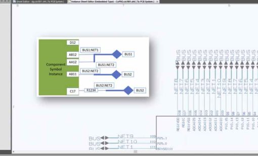
This webinar introduces a solution that automatically updates the pin assignments of ICs and complex connectors in PCB designs by reading pinout lists of SoC modules and multi-pin connectors into CR-8000 Design Gateway and automatically creates all required connections, buses, and hierarchy links in the schematic.
In this webinar you will see how Design for Test (DfT) using TestWay from Aster Technologies can be integrated into a CR-8000 design flow to allow users to analyze their design at each stage of the design to delivery workflow, avoiding the traditional problems associated with traditional post-layout testing, prior to transfer of the CAD data to production.
Failing to adhere to Electrical insulation requirements could prevent your product from being released. Zuken's CR-8000 constraints management and safety standard checking tools can help you meet the required IPC standards.
CR-8000 advances system-level PCB design with significant enhancements in analog simulation, SI analysis, and intelligent layout and routing
Our Satisfied Customers
Related Products
System Planner provides a system-level design environment for the architectural planning and optimization of electronic systems and products.
CR-8000 Design Force is the fastest, most effective PCB design solution available today. Design Force enables design teams to layout and verify their designs in the context of a complete system or product.
DS-CR supports the specific demands of PCB design data management. It combines multi-site library, design data, and configuration management capabilities into a unified engineering environment.
See how CR-8000 Design Gateway addresses the most challenging design tasks
Design Gateway provides complete system circuit engineering. Native and interactive integration with a wide range of signal integrity (SI), analog, digital, and multi-technology verification tools is provided. Through this it also supports the co-simulation of analog and digital functional blocks and programmable devices.
Using Zuken CR-8000 Design Gateway you can manage signal continuity (interconnects) at the system level rather than just at the design level. Design Gateway is the only tool available for creating and managing a system level schematic, allowing for pragmatic evaluation of board-to-board signal continuity.
Design Force exchanges information with the engineering frontends System Planner and Design Gateway to drive the design process and share changes between the product planning and circuit design disciplines. This allows design teams to create multi-board designs without unnecessary iterations during the design process.
Related Blog Posts
In part 1 of this series, I introduced the different methods for multi-board design in CR-8000. In most cases, the design starts with a system circuit diagram. Today you'll learn how to create and verify one in CR-8000.
Multi-board designs are becoming increasingly important as today's products require higher speeds and more complex circuits in smaller dimensions. There is more than one way to create multi-board layouts in CR-8000.
This video shows how users can simulate and analyze Analog circuit design in the CR-8000 Design Gateway interface with the PSPICE simulation tool.
And it's easier than you think. A reuse library can boost productivity and product reliability. Read and watch our video to learn more.
Follow along with this step-by-step video and learn how to import DXF data into the CR-8000 Design Gateway symbol editor.
There’s a greatly improved option in CR-8000 Design Gateway 2018 that gives users the opportunity to add multiple sheets when creating new designs or when adding sheets to an existing design.
