Design data and decisions are traceable providing history and documented variance to plan. Minimize risk
The digital transformation of engineering and production promises a sustainable improvement of business efficiency and profitability. A recent IDC study showed that 90% of small and medium-size businesses are budgeting for the digital transformation and 73% have begun the process.

Design data and decisions are traceable providing history and documented variance to plan. Minimize risk

The model-based design offers multi-discipline requirements, behavior, and architecture defined in a single source of truth

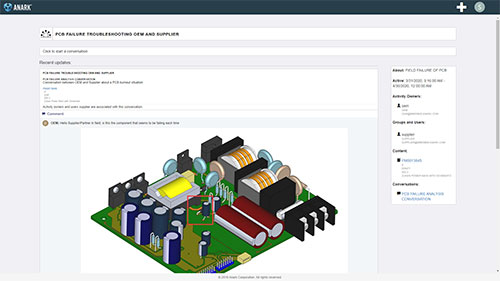
Through communication tools, conversations can be associated with technical data packages for signoff and traceability.

A key function of the Digital Thread is to enhance communication through online conversations spanning internal and external organizations.
The model must remain relevant throughout the product life cycle. This is one of today’s biggest challenges. The model typically becomes a Systems Engineering artifact and has limited use through the development and manufacturing process. A Digital Engineering process keeps the model relevant through the product life cycle providing ROI benefit.


The system-level model is decomposed into electrical and electronic subsystems for implementation. Each subsystem is composed of sensors, ECU’s, interconnects, etc. Each of these design elements must be defined in terms of a design envelope which provides the design teams with the implementation parameters. Verification requirements are made against the design envelope to assure that the implementation fulfills the intent of the model.
The model-based design has verification gates to ensure that the implementation reflects the model definition. The verification gates are comprised of design reviews, trade-offs, changes and ultimately approval. The digital conversations behind those activities and approvals become part of the digital thread. Verification gates are placed at critical design phases that include architecture, design, first article, and subsystem. Each gate requires a status update in the model.


Digital Engineering requires a digital communication mechanism to replace paper trails and documentation. A robust digital thread implementation provides a browser-based communication built on activities, conversations, groups, and data. All digital activity that can span the product life cycle is captured and can provide traceability.
The process is based on a model built upon relationships. The model replaces a document-based design. The model is typically created by the Systems Engineering team who converts system purpose into structure, behavior, and requirements. The model is considered the single source of truth.
The model must remain relevant throughout the product life cycle. This is one of today’s biggest challenges. The model typically becomes a Systems Engineering artifact and has limited use through the development and manufacturing process. A Digital Engineering process keeps the model relevant through the product life cycle and operates as a single source of truth.
For the purpose of realizing the model in the electrical and electronic domains, the model must be decomposed into E/E subsystems. These subsystems are further decomposed into functional elements as Electronic Control Units (ECU), sensors, busses, and connections.
Realizing the model in the electrical and electronic domain requires a logical structure of design elements with the associated behavior and requirements. Model creation can be done with Vitech’s GENESYS product with the appropriate guidelines for model content. For instance, the model does not typically contain specific component identification such as part numbers.
When the design transitions from System Engineering to the implementation team, a design envelope must be clearly defined. The design team then knows what are the acceptable parameters in terms of cost, weight, size, power, etc.
Architecture verification is a design step prior to a detailed design where a partial detailed design is used to verify model requirements that can be met at high confidence. If a requirement can not be met at this phase, Systems Engineering must alter the model in the context of the entire system to enable a realizable implementation of the mode.
Once the design is verified at the architecture level meaning the verification requirements are met with high confidence, the design can move to detailed design. At this point domain-specific electronic and electrical design practices and tools are used to design a manufacturable product. Learn more about transitioning to electrical design.
The model must remain relevant through the product development process. This is accomplished through verification gates which are comprised of a set of verification requirements. The design can not proceed to the next development phase until the gate requirements are satisfied. This ensures the product is consistent with the model.
As the design moves through each verification gate, the model must be updated to reflect the verification requirement status. This allows Systems Engineering to monitor the design progress in terms of meeting verification requirements. As the design progresses through the implementation process, Systems Engineering has a window into its model consistency.
Throughout the Digital Engineering process, discussions that lead to decisions must be recorded and retained for traceability. The Digital Thread provides the mechanism to hold those critical digital conversations.
Related Resources
Zuken a signé un accord de développement conjoint avec IBM pour innover dans l'intégration 3D des circuits, accélérer le hardware pour AI et optimiser les workflows EDA. Cette collaboration se concentre sur l'intégration hétérogène de puces, l'évaluation des accélérateurs d'apprentissage profond, let les tests de fiabilité. Ce partenariat souligne l'engagement de Zuken à stimuler l'innovation dans la conception de puces alimentées par l'IA et les solutions de packaging de semi-conducteurs de prochaine génération.
CR-8000 Webinar: Zuken recently announced the upcoming release of the industry’s first AI-based PCB place and route product - Autonomous Intelligent Place and Route (AIPR) - This webinar will examine how companies and users will benefit.
This white paper introduces a solution that combines the innovative approach of Model-Based Systems Engineering (MBSE) with the best practice of managing data and processes in a PDM system.
Explore how Zuken’s E3.series integrates seamlessly with leading MCAD tools like Siemens' NX and Solid Edge, Dassault's CATIA V5 / V6 and SolidWorks, PTC’s Creo, and Autodesk’s Inventor for efficient harness design - includes a detailed demonstration of how Siemens NX can be integrated with E3.series.
Discover how Zuken’s CR-8000/DS-CR integrates with Dassault Systèmes’ 3DEXPERIENCE Platform, providing robust solutions for efficient data management and collaborative workflows between electrical and mechanical design teams.


