The model is programmatically transferred and exposed to the design team.
MBSE for electrical subsystem design will be one of the cornerstones for the adoption of Digital Engineering practices. The model must be decomposed into electrical subsystems that can be realized through implementation. Programmatically moving the subsystem to detailed design is a vital step for success. Maintaining model relevance through the product life cycle enhances MBSE ROI.

The model is programmatically transferred and exposed to the design team.

The model provides a design envelope for the design team.

Model changes are sourced from Systems Engineering.

This methodology preserves the model as the single source of truth.
The optimal model content for electrical subsystem design is a reflection of your design process. The model is used to define the design envelope and not the implementation. Manufacturing part numbers and wire gauge are not typically not part of the model. Weight, cost and other requirements create the design envelope.
The design envelope moves from GENESYS to E3.series through a model importer. The import programmatically moves the logical architecture into E3.series to begin implementation. The model interfaces will be converted to wire harnesses by the design team.
E3.series has a connection back to the model so the design team can see requirements, diagrams, and parameters. This information is only exposed to the design team and not transferred to preserve the model’s integrity and a single source of truth.
Any design verification requirements that can not be met are communicated back to Systems Engineering via a requirement status.
The model presented to the design team contains requirements and structure. The design team must verify that the design envelope can be realized through implementation and that it is not over-constrained. The architecture must be verified against the model prior to going into detailed design. If a weight, power or cost requirement can not be met at the architecture phase, the discrepancies must be resolved with Systems Engineering before proceeding.
A Digital Engineering process requires that the model remain relevant throughout the product life cycle. Making the model relevant involves recording the verification requirement status at each design phase or verification gate. Systems Engineering or management can review the verification requirement status at each gate to determine the progress of the development process.
Digital Engineering requires the elimination of paper documentation and a data management ecosystem. Maintaining a single source of truth and minimizing the duplication of data across systems is paramount to a successful Digital Engineering process. The MBSE data management ecosystem consists of the MBSE tool, an Engineering Data Management (EDM) system, a PLM system and a Digital Tread backbone for digital communications. Each data thread serves a specific purpose and should remain separate.
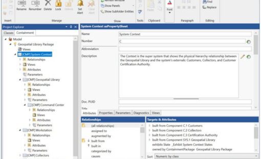
Model creation using GENESYS from Vitech provides the ability to connect to Zuken’s E3.series solution for wire harness design and manufacturing. Following design guidelines, while utilizing GENESYS provides a programmatic path to implementation while maintaining model relevance through the product life cycle.
For the purpose of realizing the model in the electrical and electronic domains, the model must be decomposed into E/E subsystems. These subsystems are further decomposed into functional elements as Electronic Control Units (ECU), sensors, busses, and connections.
Realizing the model in the electrical and electronic domain requires a logical structure of design elements with the associated behavior and requirements. The model does not typically contain specific component identification such as part numbers.
When the design transitions from System Engineering to the implementation team, a design envelope must be clearly defined. The design team then knows what are the acceptable parameters in terms of cost, weight, size, power, etc.
Once the design envelope is defined for the cables, the architecture composed of blocks and interfaces transfers to E3.series. The requirements, constraints, and diagrams are exposed and viewable from E3.series.
The design team will be able to see diagrams, requirements and parameters from E3.series. The data is not transferred to E3.series to preserves the single source of truth of the model.
Architecture verification is a design step prior to detailed design where a partial detailed design is used to verify model requirements can be met at a high confidence. If a requirement can not be met at this phase, Systems Engineering must alter the model in the context of the entire system to enable a realizable implementation of the mode.
The model must remain relevant through the product development process. This is accomplished through verification gates which are comprised of a set of verification requirements. The design can not proceed to the next development phase until the gate requirements are satisfied. This insures the product is consistent with the model.
As the design moves through each verification gate, the model must be updated to reflect the verification requirement status. This allows Systems Engineering to monitor the design progress in terms of meeting verification requirements. As the design progresses through the implementation process, Systems Engineering has a window into its model consistency.
Throughout the Digital Engineering process, discussions that lead to decisions must be recorded and retained for traceability. The Digital Thread provides the mechanism to hold those critical digital conversations.
Related Resources
Check our latest webinars, white papers and more
Zuken annuncia le novità della release E3.series 2026, che introduce potenti funzionalità per ottimizzare la progettazione elettrica e fluidica, rafforzare la collaborazione interdisciplinare e incrementare in modo significativo la produttività ingegneristica.
Zuken Inc. has joined the JOINT3 consortium—an industry co-creation platform led by Resonac to accelerate the development of next-generation semiconductor packaging materials, equipment, and design tools for panel-level organic interposers—where Zuken will contribute its CR-8000 Design Force expertise to help demonstrate, optimize, and evolve design and manufacturing processes that address the growing demand for 2.xD and 3D semiconductor packages in applications such as generative AI and autonomous driving.
Zuken apre un nuovo centro di sviluppo per E3.series a Neu-Ulm
This latest release of GENESYS 2025 focuses on enhancing model structure, streamlining interoperability between tools, and accelerating the adoption of key industry standards that are vital for designing large-scale mission-critical and enterprise systems.
Explore CR-8000 2025’s latest AI and simulation upgrades for faster, more reliable schematic and layout design—optimized for high-speed, high-density electronics.
Related Blog Posts
Executives’ Perspectives on Digital Transformation #3
Executives’ Perspectives on Digital Transformation #2 The Productivity Paradox
Executives’ Perspectives on Digital Transformation #1 Building Dynamic Capabilities for Product Success in a Changing World
Auguri di Natale da Zuken! Auguri di un Sereno Natale e Felice Anno Nuovo - Qui di seguito troverete informazioni relative al servizio di assistenza.
