
3 Methods for Routing High-Speed PCB Designs
When discussing printed circuit boards, designs usually fall into two categories: traditional PCBs and high-speed PCBs. For a traditional PCB design, the component pins in the same net simply need connections with copper traces. In modern high-speed PCB designs, design engineers must connect the traces while also considering many other factors to satisfy the high-speed signal integrity requirements. This post will look at 3 methods for routing high-speed PCB designs from the foundation of constraint management to specific high-speed PCB routing features.
Can Your Tool Manage High-Speed PCB Designs?
I mentioned that routing high-speed PCB designs requires the design engineer to consider additional factors. These can include impedance match, timing skew, crosstalk, sequence routing, via and/or connector (package) impedance mismatch, even continuous power/ground plane pouring designs. In addition, designers need to be sure that their layout tool can provide the routing functionalities required for high-speed PCB designs. Are you working on high-speed PCB designs? Is your tool robust enough to manage high-speed PCB designs?
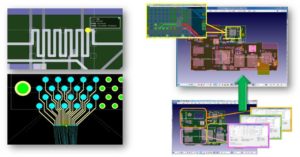
CR-8000 Design Force is a PCB layout design tool well-known for its ability to quickly and accurately tackle the most challenging high-density PCB designs. The tool also has several built-in methods crafted especially for routing high-speed PCB designs.
Constraint Management is the Essential Foundation
Before discussing the specifics of any routing method, it is essential to have routing constraints in place. Constraints will guide any auto, interactive, or manual routing process with online/offline DRC. A robust constraints management system serves as a foundation and enables effective routing methods for high-speed PCB routing.
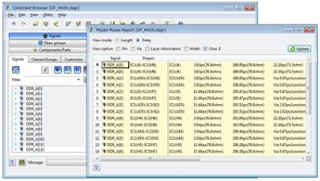
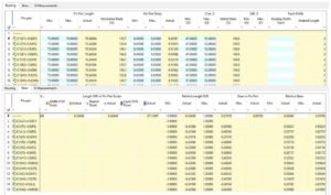
CR-8000 Design Force Constraint Browser is specially designed for this purpose. It can define E-net-based high-speed constraints as well as pin-pair level constraints. These constraints include length and skew, trace width/impedance, number of vias, etc. They can be defined and used for online/offline DRC from schematic entry to PCB layout design and auto/interactive routing.
Methods for Routing
Now that we’ve established the importance of constraints, let’s take a closer look at 3 methods for routing your high-speed designs:
1) Impedance Controlled Method
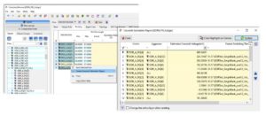
Impedance mismatching is the most critical routing issue in high-speed PCB designs. When using this routing method, impedance control needs to be from the layer stack-up design. CR-8000 Design Force allows the user to define the trace width for each layer. At the same time, it provides the characterized impedance from the field solver. Differential pair trace width and spacing are also set as separate rules for impedance calculation. DRC can use these settings for online and offline checking.
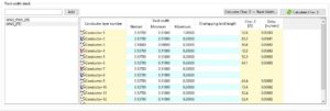
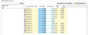
Besides the characterized impedance calculation on a layer stack, Design Force Constraint Browser also provides single net impedance settings (max/min). These settings can serve as constraints for auto and interactive routing.
2) Skew Controlled Method
We often see the use of skew control in parallel interface designs. These designs require the timing skew to match between data signals, data and strobe, clock and address, etc. Although there are some unique ways to compensate for timing skews, the easiest and most cost-efficient way is to make the trace length match in the routing.
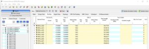
The CR-8000 Constraint Browser can add maximum and minimum constraints for pin pair length, calculated pin pair delay, and trace impedance. It also lists the values for relative length difference, pin pair length difference, and relative skew. The tool automatically takes all constraints into account for auto and interactive routing with real-time DRC checks. It allows the auto and interactive routers to use these constraints in tandem to complete all related net routings.
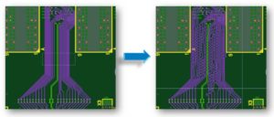
3) Differential Pair Routing Method
Differential signaling is a good choice for high-speed designs with critical high-speed nets. One of its major benefits is a self-looped return path. This special self-looped return path can cancel the opposite signals resulting in resistance to incoming interference and reduction of outgoing EMI and crosstalk. When using this method, it requires some specific routing constraints:
- Length and length matching – keep it equal!
- Width and spacing – keep it constant!
- Impedance – minimize variations!
CR-8000 has all of these particular constraints built into the constraint browser and auto/interactive routing. Using specific differential pair routing methods, design engineers will experience more accurate and efficient routing for their differential pair signals.
Critical Functionality
To assist the design engineer, the tool you’re using needs to contain specific features for routing high-speed PCB designs.
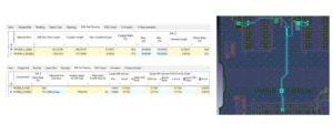
Crosstalk Estimation
Signal crosstalk is a significant concern for high-speed PCB designs. Regular crosstalk simulations typically take a long time to finish. Crosstalk estimation uses a calculation-based method so it can arrive at a result and quickly provide feedback. The result can serve as a reference for repeating the best routing outcome on future designs.
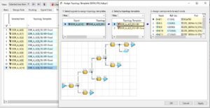
Topology Template
When working with critical high-speed signal nets, design engineers may need to route the segments in sequence. Using Topology Template as a special constraint will guide the correct routing of these nets. Designers can use this constraint for manual, auto, and interactive routing.
Auto-interactive Routing and Lengthening
Sometimes, PCB designers encounter a design with a group of high-speed signal nets, such as DDR. These types of nets require constraint management to guarantee successful routing. Manual routing often proves too difficult, but auto-routing, interactive routing, and lengthening features can help route the board quickly and correctly.
Summary
Routing high-speed PCB designs requires the analysis from Signal Integrity and Power Integrity simulations, as you would expect. But these modern designs also require the newest routing methods created specifically for high-speed signal nets. As new technologies continue to evolve, your design tools need to keep pace.
A high-speed design-ready PCB tool must contain features to address both traditional and high-speed PCB designs with high-speed signal routing methods. A robust and capable tool will include high-speed constraint management, differential pair routing, skew and impedance controls, and more.
CR-8000 is such a tool and can assist with routing high-speed PCB designs. In addition to the many advanced functionalities noted in this post, it also contains many other powerful features to address your PCB and IC packaging design needs. From multi-board design and analysis to 3D MCAD integration, CR-8000 is the tool for all of your most challenging designs.
—-
References
- High-Speed Design and Analysis Using CR-8000 – Zuken US
- High-Speed PCB Design Analysis Phases and Constraint-Driven Methodology – Zuken US
- The Why and How of Differential Signaling, Carsten Pinkle, https://www.allaboutcircuits.com/technical-articles/the-why-and-how-of-differential-signaling/

- Blog

- Blog
- Blog

- Blog
Related Products & Resources

- Blog

- 2020 Technical Webinars
This webinar will explore a high-speed design process in CR-8000 that utilizes a constraint browser, topology template, crosstalk estimation, signal and power integrity simulations.

- Products
Building a competitive product today is much more difficult than a few years ago. Existing PCB-centric design processes are limited to a single PCB and do not provide the necessary tools for today’s competitive product development environment. PCB-centric design processes are falling behind.

- Blog