4 Essential Features for High-Speed PCB Design and Verification
Menu
Following the spectacular technological evolutions we’ve seen in recent years, high-speed PCB designs are moving to a new stage. Faster communication networks and memory I/O speeds demand that multi-GHz signals transmit in backplanes, cables, packages, connectors, and boards. You will find this to be the case in virtually every modern electronic device. This increased demand for speed in electrical designs requires updated tools for high-speed PCB design and verification.
More portable and battery-powered devices require engineers to focus on transceivers and low-energy designs. At the same time, there is greater demand for more RF and digital mixed-signal designs and less margin for power delivery network designs. These factors indicate the heightened importance of Signal Integrity, Power Integrity, and Electromagnetic Compatibility simulations. Adding to the complexity, modular and reusable designs require model interoperability.
To address these challenges, Zuken’s CR-8000 now includes several exciting new features for high-speed PCB design and verification. Let’s take a look:
Feature 1: S-parameters/Touchstone® Handling and Simulation
S-parameters–a term that refers to the scattering matrix of a microwave network–first appeared in the 1960s. Then, in 1984, EEsof (part of Agilent Technologies at the time, now Keysight) filed to trademark the word Touchstone, referring to a standard ASCII file format. Following that, the IBIS Open Forum ratified Touchstone® 2.0 file format in 2009.
S-parameters/Touchstone® modeling is gaining popularity in SI, and PI analysis for faster signal transmission speed on PCB and package interconnects.
S-parameters has the accurately characterized interconnect behavior for wideband multi-GHz signals. And it automatically correlates with lab measurements. It has been in use for microwave designs for many years. Touchstone® is an international standard specification, and the tabular ASCII format is great for interoperability.
However, S-parameters/Touchstone® is not a silver bullet. Without careful handling, S-parameters models often have these issues:
- Data is not passive and causal
- Insufficient data for the correct DC solution
- Frequency range is too narrow
- Incorrect measurement techniques or bad data
- Inaccurate or unavailable node definitions
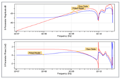
CR-8000 Design Force supports S-parameters/Touchstone® models through its Simulation Model Library (SML). It recognizes SnP file formats and provides the functionalities for sanity checks:
- Syntax checks
- Reciprocity, Causality and Passivity checks
- Graphical matrix and data views
Furthermore, CR-8000 Design Force enables imports and converts data into broadband SPICE with selectable enhancement and extrapolation functions. It also provides virtual RAW and Enhanced data comparison, and a status/error report.
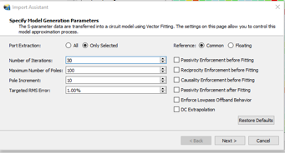
With the latest release, CR-8000 Design Force supports S-parameters/Touchstone® models from generation to simulation. It enables engineers to use it for correlations between simulations and measurements in order to better predict system performance and cost through simulations.
Feature 2: IBIS Power-aware Model Support and Simulation
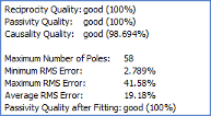
An IBIS power-aware model might also be called an IBIS PDN model. It was enhanced from the original IBIS buffer model, which always uses the ideal power supply source for simulations. An IBIS power-aware model contains more characterized data and includes the traditional IV/VT curves. [Composite Current] is the one related total supply current (including pre-driver current); Another is [ISSO_*], where * represents Pullup. Pulldown, Power Clamp, and Ground Clamp, provide the information for power supply gate modulations.
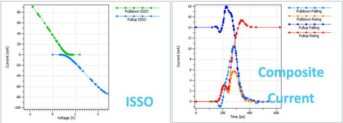
CR-8000 Design Force supports IBIS PDN models. It will be automatically considered if Package and Pin Mapping is fulfilling the requirements for PDN analysis.
With evolving technology, tighter design margin budgets, and the growing popularity of low-power designs, IBIS PDN models are becoming increasingly crucial for high-speed PCB design and verification.
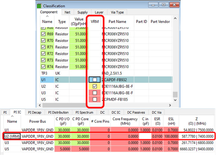
Feature 3: Voltage Regulator Module (VRM) Model Support for Power Integrity Analysis
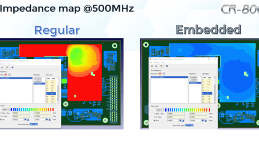
Voltage Regulator Module (VRM) is frequently used for Power Integrity analysis. VRM models present the impedance (especially low impedance) more accurately below the 10 MHz frequency range.
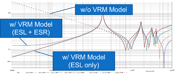
CR-8000 supports VRM for Power Integrity analysis. It provides a simple user interface by clicking the check-box for turning IC to VRM. The tool will automatically replace the IC model (series R-L-C) with a VRM model (series R-L or series L). Users can easily edit these parameters in the PI IC view on a per-IC basis in each power bus.
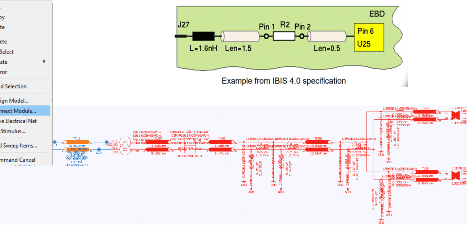
Feature 4: IBIS EBD Model Support and Analysis
Modern products are using more modules and reusable designs, for example, DDR memory cards, portable storage devices, etc. As a result, IBIS EBD (Electronic Board Description) is seeing greater usage in the past year or two. As an industry standard, IBIS EBD provides superior interoperability and IP protection benefits.
In the latest CR-8000 Design Force release, the user can load IBIS EBD models into Simulation Library Manager (SLM), and the software will treat them as simulation components.
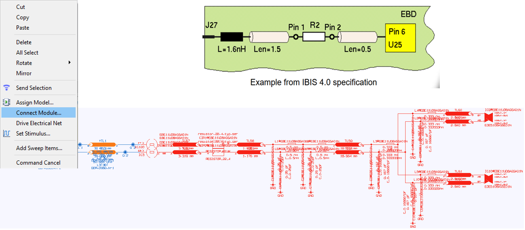
The Connect Module command in the Electrical Editor can connect the EBD model, and the Simulation Library Manager will display it as a module. From there, the user can simulate and view the net structure and element values to better understand the modular structure and debug SI issues more easily.
Summary
Zuken added these four new critical simulation features to the latest release of CR-8000 to help improve high-speed PCB design and verification capabilities for users. The new features enable the benefits of multi-GHz, low-power, modular design and verification. At the same time, CR-8000 provides simulation capabilities and mitigates errors in format conversions for high-speed PCB designs.
For more details, please visit our website.

Lance Wang is a solutions architect at the Zuken SOZO Center. He supports the CR-8000 product line, mainly focusing on high-speed PCB design and signal integrity features. When not behind the keyboard or in front of customers, he is a Tom Brady fan and enjoys playing ping pong in his spare time.

- Press Release
March 24, 2025
Zuken Joins IBM Research AI Hardware Center to Develop Next-Generation AI Hardware Solutions
Press Release, Zuken USA
- Blog
March 11, 2025
Tech Tip: How to Standardize Your PCB Design Settings in CR-8000
How to..., PCB Design, Tech-Tips, CR-8000 Tech Tip, Tech Tips, V2023, Blog
- Blog
January 23, 2025
Optimizing PCB Performance with Embedded Capacitance
cr-8000, Electronic, PCB Design, Embedded Capacitance Embedded Capacitance, PCB design PCB design, PCB Simulation PCB Simulation, Blog

- Blog
January 16, 2025
The Convergence of Technology and Electrical Design Take Smart Robotics Mainstream
Electrical, Electronic, Artificial Intelligence, Electrical Design, Electronic Design, Robotics, smart robotics, Blog
Related Products and Resources
- Blog
March 11, 2025
Tech Tip: How to Standardize Your PCB Design Settings in CR-8000
How to..., PCB Design, Tech-Tips, CR-8000 Tech Tip, Tech Tips, V2023, Blog
- Blog
January 23, 2025
Optimizing PCB Performance with Embedded Capacitance
cr-8000, Electronic, PCB Design, Embedded Capacitance Embedded Capacitance, PCB design PCB design, PCB Simulation PCB Simulation, Blog
- Blog
January 16, 2025
The Convergence of Technology and Electrical Design Take Smart Robotics Mainstream
Electrical, Electronic, Artificial Intelligence, Electrical Design, Electronic Design, Robotics, smart robotics, Blog

- Blog
January 09, 2025
Top 10 Blog Posts of 2024
Americas, cr-8000, Data management, e3-series, Electrical & Wire Harness, PCB Design, 2023, CR-8000, E3.series, Electrical Design, PCB design, Top 10 Blogs, Blog