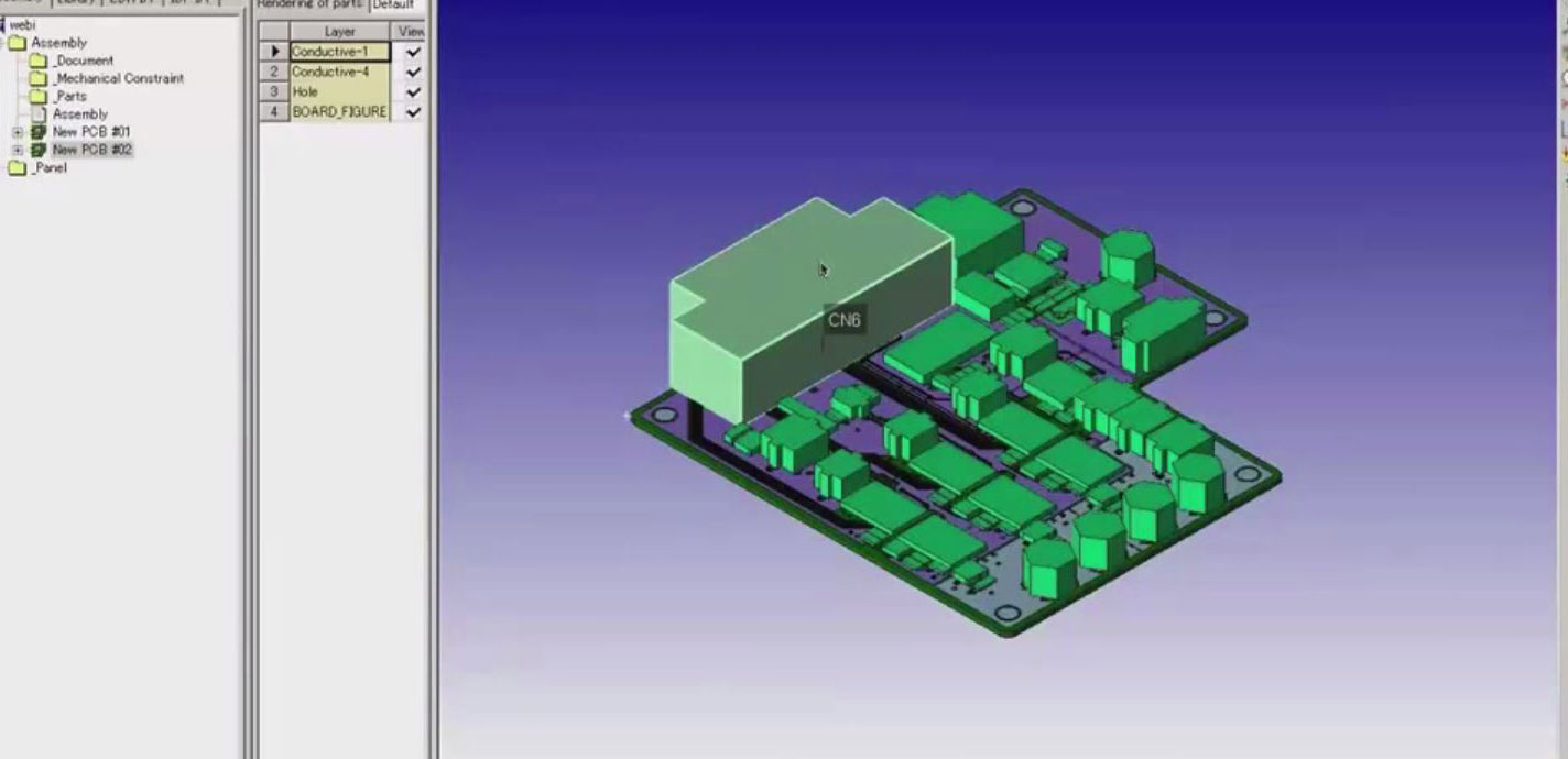
If you’re a PCB designer, electrical engineer, or mechanical designer, you know that communication between electrical (ECAD) and mechanical (MCAD) departments can be tedious, and a real pain in the neck sometimes. It’s almost like you finish your design, throw it over the wall into the next cubicle…and then just cross your fingers in hopes that everything fits together. You’ve probably also learned – the hard way – that reworking your designs over and over costs the company time AND money. But maybe what you don’t know is that it doesn’t have to work this way.
Here are 5 key reasons why you should be viewing your electronics design in 3D:
- Improve collaboration between mechanical and electrical engineering.
- Reduce design cycle time by minimizing iterations between design departments.
- Maximize the efficient use of available space in an electro-mechanical assembly.
- Utilize standard neutral file formats (IDF & STEP) to read PCB and mechanical files into Board Modeler.
- Check collisions, violations and problems in your design; resolve problems, and back annotate them into the respective systems in the same neutral file formats.
Enter CR-5000 Board Modeler, and a whole new way of working. What’s really great about Board Modeler, is that it works with ANY of the popular PCB or Mechanical systems out there. So if you’re using Cadence Allegro with Siemens NX, or Mentor Expedition with Dassault’s CATIA V5…or any other combination, we’ve got you covered. If you’re using CR-5000 Board Designer, even better, because you already know what Zuken’s software is capable of.
Adding Board Modeler to the mix can help you take even the most complex, time-consuming design process and streamline it. Using neutral file formats like IDF and STEP, you move your designs through Board Modeler, streamlining data flow while checking for collisions, violations, and other problems. PCB and mechanical designers alike get an accurate virtual 3D view of the entire product, so you can see early on how a board and its components will fit into the enclosure and make the most of the space you have. When you have this information upfront, you can design it right – from the start – with far fewer errors and rework.
Related Products and Resources

- Products
Today’s Desktop PCB Design tools require better connectivity to the outside world. eCADSTAR offers a newer level of connectivity that brings users closer to their parts providers than ever before. This allows Engineers to selected parts and drag them directly to their design. Add the additional functionality of high power Signal integrity verification and Power integrity analysis and you have the Ultimate Desktop PCB Engineering solution.

- Products

- Products
Building a competitive product today is much more difficult than a few years ago. Existing PCB-centric design processes are limited to a single PCB and do not provide the necessary tools for today’s competitive product development environment. PCB-centric design processes are falling behind.
