
5 Steps to More Effective Mechatronic Cable Design (Part 2)
Menu
This is the second in my two-part series that looks at the functional aspects of electrical design that you, as an electrical engineer, should be collaborating with mechanical engineers on. Here you can find the first post.
Previously I talked about:
- Defining Cable Sizing
- Calculating Bend Radii
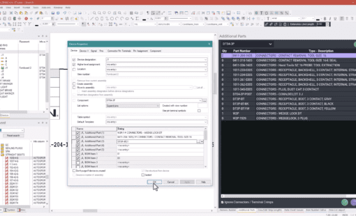
- Selecting Additional Parts
Today I’m going to focus on:
- Optimizing Cable Routing
- Manufacturing a Cable Harness
Optimizing Cable Routing
Electrical engineers design in the logical world, connecting one connector to the other. Without any degree of up-front collaboration with the mechanical engineer, you have a limited ability to factor in the route that the cable is going to physically take as it passes through the space. This route may involve working around obstacles which calls for the integration of additional parts such as bulkhead connectors or a junction box. With the mechanical data on hand you can be far more knowledgeable and in a position to make more informed design choices about the cabling and even make suggestions to the mechanical team that would allow the design to be optimized.
Example: An electrical engineer involved in the design of a machine that is being manufactured remotely in another country transfers the cable design into a mechanical system for routing from the control panel to a sensor when he realizes that there is a piece of sheet metal in the way. Ordinarily the Mechanical Engineer would have routed the cable around the sheet metal, which would have resulted in much more cable being used and increasing potential noise and interference issues. Instead s/he approaches the mechanical engineer and establishes whether this is load bearing or not – whereupon they agree on a workaround that involves a hole being punched in the metal for the cable to pass through – ultimately improving the design and saving money.
Manufacturing a Cable Harness
Cost effective manufacturing involves careful management of materials, and when it comes to cables, it typically refers to the length of wires and cables required, as cables that are too short have to be scrapped and cables that are too long waste money. Again this data can only be obtained by combining the electrical logical world with the mechanical physical 3D world.
Conclusion
So that’s my top five. If you’re not already using E3.cable it might be time for you to check that out too. It’s great at enabling electrical engineers to collaborate with mechanical engineers for more efficient, high quality product design.
As I mentioned last time, we do also have an OnDemand webinar available for more Mechatronic collaboration design tips.
- On Demand Webinar: Streamlining Electrical System Design through Mechanical & Electrical Collaboration
Below is a two minute preview of what to expect within the webinar, or select the link above to access the full 40 minute webinar, including software demonstration.
If you have any questions about electrical and mechanical collaboration or more suggestions to add to my list of five, why not add a comment and let’s get a discussion going.

- Blog
February 20, 2025
Making Sense of Wire Groups in E3.series
e3-series, Electrical, Electrical & Wire Harness, Database Editor, E3.series, E3.series Database Editor, Blog

- Press Release
February 18, 2025
Zuken USA Announces Tech Tour 2025 to Highlight the Latest Innovations in Wire Harness and Control Panel Design
Press Release, Zuken USA
- Blog
February 04, 2025
Tech Tip: How to Display Additional Parts in the Device Tree
e3-series, Electrical & Wire Harness, How to..., Tech-Tips, E3.series, E3.series 2025, Blog

- Blog
January 30, 2025
Transforming the Wire Harness Design and Optimization Process
Automotive, e3-series, Electrical, Electrical & Wire Harness, E3.series, Blog
Related Products and Resources

- Test Drive
June 20, 2019
Cable Design Software Evaluation
Test Drive, Zuken USA
Test Drive E3.cable

- Products
November 16, 2018
Electrical Library & Data Management
Electrical and Fluid Data Management
- Products
October 26, 2018
Electrical Schematic and Wiring Diagram Design Software
E3.schematic
- Products
October 24, 2018
E3.series
E3.series is a Windows-based, scalable, easy-to-learn system for the design of wiring and control systems, hydraulics and pneumatics. The out-of-the-box solution includes schematic (for circuit and fluid diagrams), cable (for advanced electrical and fluid design), panel (for cabinet and panel layout), and formboard (for 1:1 wiring harness manufacturing drawings). Integrated with MCAD, E3.series is a complete design engineering solution from concept through physical realization and manufacturing output.
Read now
E3.series