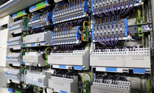
Follow along with this comprehensive guide to learn how to start creating panel parts for E3.series and find answers to the most common library questions.
By the end of this post, my goal is to help you discover the importance of panel database parts and learn how to construct them. As well as gaining insights into how your library can help drive downstream manufacturing, assembly, and service processes, empowering you to streamline your engineering and manufacturing endeavors effortlessly.
We need to answer three main questions: Why are they important, how do I make them, and how will they help with future tasks?
#1 – Why do panel database parts matter?
The most obvious reason is that you need a library to make the panel design. The foundation for successfully creating any design is a well-built library. But what are the other reasons why databases matter?
Designing parts correctly helps reduce spacing and layout issues during assembly.
In E3.panel, you can create a 1 to 1 physical representation of your control panel design. You can define special requirements for each component, like mounting options and restricted areas. For example, if you need to mount a part on a specific rail type. Another example is if you need to leave a certain amount of space for accessibility or heat generation.
You can reduce the number of wiring errors for production.
You are building a digital twin model for each component to the actual part. For your parts to be accurate, you must define each connection point’s locations and properties. The connection properties allow you to set design rules, such as if the cavity requires a particular part, the wire gauge range, and limit the connecting wires to a set amount. When connecting to the device, E3.series is actively checking these design rules in the project for error prevention. This preventative measure would eliminate an issue a designer might not have found until the design hit manufacturing. Causing a stop build, rework, and wasted material.
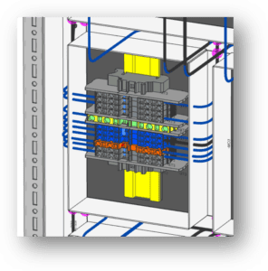
A significant advantage to building panel layouts to scale is the ability to generate accurate wire routing information.
In addition to leveraging the automatic panel wire routing, E3.series also provides real-time automatic wire length calculations. Manufacturers can take this information and drive wire processing machines to cut, mark, and strip wires for production. A direct connection to wire processing machines eliminates the need for error-prone manual length calculations and reduces wire waste.
#2 – How do I build panel parts for my library?
We offer various options for our customers to get full database training along with helpful how-to videos, tips, and tricks. For our maintenance customers, the Zuken Community is an excellent resource for learning. This post will focus on the main types of control panel library components.
Basic steps for constructing the main panel components
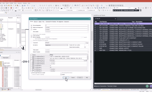
All E3.series electrical panel components contain attributes, a 3D model, and one or more symbols if required for creating electrical schematics. Librarians will also define the component name and assign the model and symbol pins. Here is what you need to consider for each item.
- Attributes: The purpose of attributes is to add any information about the physical part you want to make available in the project or reporting. Some examples are defining the manufacturer, related internal or customer part numbers, weight, cost, amp ratings, datasheet hyperlinks, and any electrical parameters to have on hand while designing. An additional use for attributes is as a filter when searching the control panel library for a part to use.
- Models: Panel models are a realistic 3D representation of the component used to represent the physical size required. With the STEP model import license, you can import a STEP model provided by the manufacturer, which will add the 3D model and all the 2D views of the part. The model also includes the information mentioned above, like restricted areas, cutouts, drill holes, mounting requirements (slots), and pins with wiring allowances.
- Symbols: Most symbols represent the logical connections of the components in the electrical schematics for the control panel. These symbols include pins that are assigned to pins on the model. Librarians can design symbols to follow any required standard, i.e., IEC, ANSI, etc. Panel symbols are distinct symbol types that do not contain pins and represent another view of a panel component, for example, showing a push button on the front side of the door.
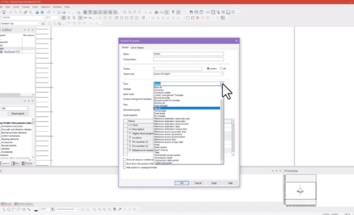
Building a new control panel library part might sound complex, but after watching the detailed video tutorial, you will see how simple it is.
Create cable ducts for panel wire routing
Cable ducts are used in the panel sheet to establish a path to route a wire between two devices. They can be added as a dynamic device without a part number associated or from the database with a part number. E3.series offers users options to represent different cable duct types, whether the backplane wiring is solid, slotted/wire comb, or punched. Cable ducts can include drill hole locations which E3.CutOut includes in the export for manufacturing. Manufacturers can subsequently utilize the information for machining and drilling panels during production.
With the database-defined cable duct, you can add attribute details similar to the primary components and specify the physical properties, including size and drill hole configuration. Database cable ducts require a model set to the type of cable duct, where you input the size information and the look. You then add the model to the component where you can define attributes and the drill hole definitions.
For visual learners, the following video tutorial will guide you on building a cable duct for your library.
Design mounting rails for your library
Mounting rails are similar to cable ducts which can be added dynamically or from the database. Mounting rails, such as a rail with terminal blocks, are used for component placement. Database mounting rails also include a mount type model to define the physical properties for the size and the slot description to control mounting components on the rail. Like the cable ducts, you set the attributes and drill hole definitions on the mounting rail component level.
#3 – How does my library drive manufacturing, assembly, and service processes downstream?
In the first few sections of this post, we have discussed a lot about how the control panel library parts can aid the design portion when creating a product with design rule checks, placement aids, and more. Now let’s look at how the database can help in the downstream processes.
- Manufacturing: From the panel design, data is available for component placement, din rail and cable duct attachments, drill holes, and cutout information. This information can be configured as a project sheet or exported to an automated modification center via DXF using E3.Cutout. Manufacturing can leverage the wire and cable routing information for wire processing machines and panel wiring instructions. Additionally, manufacturers can generate a bill of materials using various methods in the E3.series suite for quoting and procurement processes.
- Assembly: Panel manufacturers can add Panel Builder for E3.series as a plug-in that provides easy-to-use, tracked, and controlled wiring task instructions for assembly—the wiring tasks as fed from the same wiring routing information automatically populated in the project. Reduce training requirements and errors by providing the assembler with visual step-by-step wiring instructions to assemble the panel.
- Service: A digital twin of the control panel provides more information for troubleshooting and modifications after the product is in service. Utilizes E3.series viewing tools, the service team can quickly view signal tracing, component, and wiring information about the design.
E3.series Control Panel Library: Your Pathway to Success
In conclusion, the E3.series control panel library is essential for engineering quality. By understanding the importance of panel database parts and mastering their construction, you pave the way for flawless project design with reduced errors and increased efficiency. Incorporate cable ducts and mounting rails to streamline wire routing and component placement, further optimizing your processes. Moreover, leverage E3.series integration in downstream manufacturing, assembly, and service tasks, reforming your approach to each stage.


