
Common Pitfalls of Wire Harness Design and How to Avoid Them
Menu
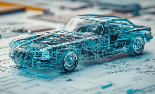
Wire harnesses are the hidden nervous system of modern electrical systems. From automobiles to the space shuttle, from agricultural vehicles to medical equipment, anything that carries power and signals across multiple electrical components relies on wire harnesses to link it all together. Optimized wire harness design is getting increasingly complex as our cars and machines incorporate smart manufacturing and advanced electronics. Here are three common pitfalls of electrical wire harness design and how to avoid them.
Wire Harness Pin Connections: Avoid Costly Mistakes

Wire harness design engineers are system integrators who connect electrical sub-systems designed by various engineers. For example, on an airplane, one engineer designs the avionics controls unit, another designs the engine, and yet another manages the cabin system. The harness engineer gathers information from all these teams and links them together using wire harnesses.
Fun fact: A Boeing 747 has an estimated 140 miles of wiring.
Each wire connects a specific pin on one end to another pin on the other. If even one wire connects to the wrong pin, the system—an aircraft, vehicle, or industrial machine—won’t function properly. The wiring schematic handoff between the electrical engineer and the harness engineer is often the first to check if two units aren’t communicating as expected.
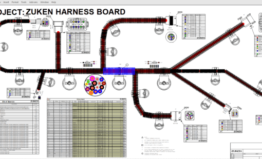
To avoid these errors, detailed electrical schematics are essential for harness connectivity validation. For instance, your car’s wiring diagram tells the mechanic precisely which wires to inspect if, for example, the power windows aren’t working due to a faulty connection to the battery. It’s quite common for the connection to span multiple harnesses, making signal integrity analysis critical to ensure correct integration and end-to-end system-level reliability.

A good schematic software will help bring information from various engineering teams. With electrical design automation (EDA) software like Zuken’s E3.series, engineers can import component pinout data from Excel or integrate with Model-Based Systems Engineering (MBSE) solutions to import component data. Schematic software can also help with signal tracing, especially if a signal traverses multiple sheets in a schematic. Lastly, tools like E3.redliner and E3.HarnessAnalyzer streamlines the design review process, allowing harness engineers to validate and correct wiring harness routing with system and component engineers.
Choosing the Right Components for Wire Harness Design
Once the electrical team confirms that the logical schematic will connect the correct pinouts of their sub-components, the harness engineer must select the right parts. The harness engineer selects part numbers for connectors, wires, and various harness accessories. These parts are chosen based on environmental factors, weight, cost, regulatory compliance, and other considerations.

Many errors in harness design arise from choosing the wrong components. For instance:
- Selecting a wire gauge that doesn’t fit in the connector pin
- Choosing the wrong terminal plating (e.g., tin vs. gold) for corrosive environments
- Using a backshell that fits the connector but doesn’t accommodate the conductor’s bundle diameter
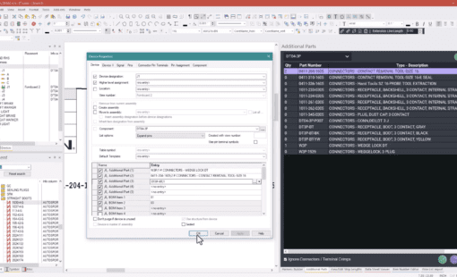
To avoid these errors, choosing components from a data-rich parts library is helpful. Library-driven electrical design software like E3.series stores information about parts such as cost, size, and material, allowing you to filter and select the proper part numbers.
The software’s built-in design rule checks (DRC) prevent common errors, while an easy-to-learn, customizable API allows for tailored checks to fit specific design needs.
Managing Wire Harness Design Revisions Efficiently
The only thing constant about life is change. Every harness engineer has received a document called design_FINAL, only to receive design_FINAL_FINAL the next day. System and component engineers try their best, but something is often overlooked. For most systems, it’s easier to fix it in the harness by swapping some wires around rather than re-manufacturing a whole new custom electronic unit.

One common pitfall is failing to track changes properly:
- Adjusting a wiring connection in one harness but forgetting its mating harness
- Updating the schematic without synchronizing manufacturing documentation
- Moving a component in CAD but failing to adjust the harness length
The solution is wire harness design software that is agile enough to handle changes. With E3.series, all diagram types are kept in sync, so all changes propagate across wiring diagrams, 3D models, and manufacturing drawings. E3.3DRoutingBridge simplifies importing changes from a mechanical model, while DS-E3 data management software makes version control and change tracking seamless.
Future-Proofing Your Wire Harness Design Process
As digitalization in manufacturing advances, the challenges of wire harness engineering continue to grow. Fortunately, wire harness design software is advancing just as fast, empowering engineers to create more reliable and cost-effective solutions.
Ready to optimize your electrical wire harness design process? Discover how Zuken’s E3.series can transform your workflow today!

-
Application Engineer
Geoffrey “Geo” Ng is an applications engineer for E3.series. His work focuses on implementation for new users and supporting long-time customers with technical demands. He has a background in Mil-Aero and enjoys childlike pursuits like superhero cartoons and board games

- Blog
April 17, 2025
What is an Intelligent ECAD System?
e3-series, Electrical & Wire Harness, AI in electrical design, Automated Wire Processing, CAD manufacturing integration, design rule checking, Digital Twin, E3.series, electrical CAD software, intelligent E-CAD, multi-user CAD environment, panel layout tools, schematic software, Wire Harness Design Software, Blog
- Blog
April 10, 2025
Accelerating Harness Manufacturing with a Smarter Digital Thread
e3-series, Electrical, Electrical & Wire Harness, Harness Builder for E3.series, Harness Manufacturing, Wire harness design, Wire Harness Design Software, Blog
- Blog
April 08, 2025
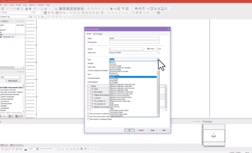
Tech Tip: Using Symbol Characteristics to Display Variations
e3-series, Electrical & Wire Harness, How to..., Tech-Tips, E3.series, E3.series Tech Tips, Tech Tips, Blog

- Blog
March 13, 2025
The Role of Electrical Engineers in Space Exploration
Electrical, Electronic, Aerospace Electronics, Electrical Engineering, High-Speed Data Systems, Power Systems Design, RF Communications, Satellite Technology, Semiconductor Reliability, Space Electronics, Space Exploration, Blog
Related Products and Resources

- Blog
February 20, 2025
Making Sense of Wire Groups in E3.series
e3-series, Electrical, Electrical & Wire Harness, Database Editor, E3.series, E3.series Database Editor, Blog
- Blog
February 04, 2025
Tech Tip: How to Display Additional Parts in the Device Tree
e3-series, Electrical & Wire Harness, How to..., Tech-Tips, E3.series, E3.series 2025, Blog
- Blog
January 30, 2025
Transforming the Wire Harness Design and Optimization Process
Automotive, e3-series, Electrical, Electrical & Wire Harness, E3.series, Blog
- Blog
January 07, 2025
Tech Tip: How to Create Custom Attributes in E3.series
e3-series, Electrical & Wire Harness, How to..., Tech-Tips, E3.series Tech Tips, Tech Tip, Blog