In order to use components more effectively in your E3.series project, you can associate a model to that component. You can describe the logical characteristics of your component using Component Wizard. However, it’s best create a model of that component to describe its physical characteristics.
Creating a model, you can render the component size, shape, pin location and physical characteristics of those pins – including the type of pin it actually is, the size and number of wires each pin can have attached to it, and the location of those pins in that component.
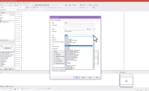
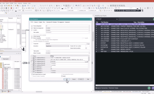
The video below demonstrates how to define and locate the pins in the graphical model and then how to associate that physical pin in the model with logical pins in the component.
Related Products and Resources
- Products

- Products
- Products
- Products
E3.series is a Windows-based, scalable, easy-to-learn system for the design of wiring and control systems, hydraulics and pneumatics. The out-of-the-box solution includes schematic (for circuit and fluid diagrams), cable (for advanced electrical and fluid design), panel (for cabinet and panel layout), and formboard (for 1:1 wiring harness manufacturing drawings). Integrated with MCAD, E3.series is a complete design engineering solution from concept through physical realization and manufacturing output.
