Understanding the complexities of calculating the Maximum and Minimum Relative Length Difference in Differential Pairs can initially seem daunting. However, this process becomes more approachable once you familiarize yourself with the basic calculation method. Let’s break it down into simpler terms for better clarity.
Calculating Minimum and Maximum Relative Length Differences
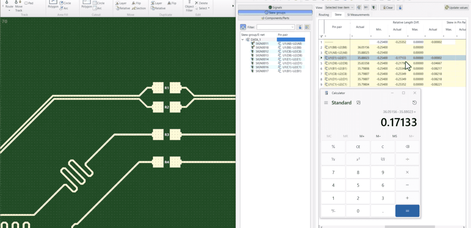
The essence of calculating the minimum and maximum relative length differences lies in comparing the lengths of two tracks within a Differential Pair Base. For the Minimum Relative Length Difference (Min) Actual, the focus is on the longer track of the differential pair, which sets the baseline for the minimum length. Conversely, the Maximum Relative Length Difference (Max) centers on the shorter track, establishing the baseline for the maximum length.
To put it into perspective, if the goal is to ensure skew group members do not exceed 0.010″ shorter than the longest base member, the Minimum Relative Length Difference would be set to -0.010. Similarly, to prevent skew members from exceeding the length of the shortest base member, the Maximum Relative Length Difference would be adjusted to 0.000″.
Importance of Skew Group Member Comparison
Skew Group members are critical components in a system, each with potentially unique timing characteristics due to various factors like distance from the source, manufacturing differences, or environmental conditions. Comparing these members to the base signal in DDR memory routing is paramount for synchronization and timing alignment.
Significant timing discrepancies between Skew Group members and the base signal can result in signal degradation, data errors, and diminished system performance. By comparing these elements, designers can implement strategies to reduce timing variances, ensuring accurate and efficient data transmission. Techniques might include adjusting signal routing, incorporating delay elements, or other methods to synchronize all signals within the Skew Group.
Demonstrating the Process
A detailed demonstration video is available to provide a more in-depth understanding, showcasing the process using CR-8000 V2023. This visual guide aims to demystify the calculation and adjustment process, making it accessible for novices and experienced professionals.


