The Digital Transformation of Shop Floor Automation
Menu
Advancements in Manufacturing Technology and Shop Floor Automation
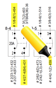
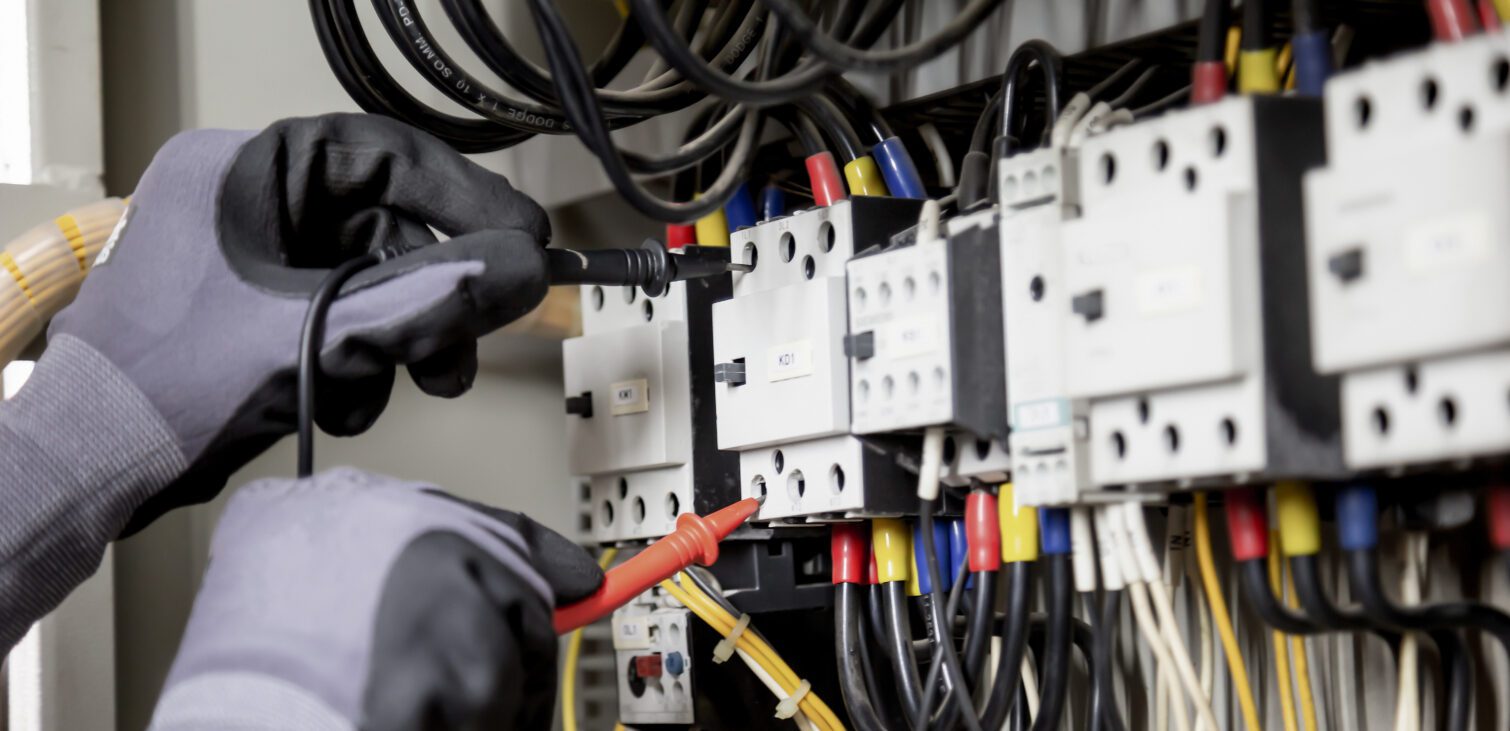
For the past thirty years, innovation in manufacturing has primarily occurred within engineering departments and not directly on the shop floor. Advances in design, like Computer-Aided Design (CAD) applications and workflow management tools, have transformed engineering processes. However, these innovations did not always translate into changes directly on the shop floor. Historically, the shop floor relied on printed paper designs and limited assembly instructions, such as electrical wiring diagrams and fluorescent yellow markup pens, to track progress. So you can understand the need to add shop floor automation.
Traditional Shop Floor Processes
On the shop floor, a typical wiring task flow might include:
- Reading and understanding wiring instructions
- Locating and drawing out wire from the spool
- Cutting and stripping the wire
- Adding termination hardware if required
- Placing the wire into the source connection pin
- Tightening to a predefined torque
- Forming the wire through cable ducts or along wireways
- Cutting and stripping the end of the wire at the destination component
- Adding termination hardware if required
- Labeling the wire
- Terminating the wire into the destination component
- Cataloging the completion of the action
This process is time-consuming and relies on manual tracking and instruction interpretation, often leading to inefficiencies, mistakes, and inaccuracies. The detailed manual method makes specific metrics about the build process challenging to monitor. Furthermore, changes between revisions are tough to manage, and a wiring diagram symbol does not easily depict the addition and removal of wires.
Modernizing the Shop Floor
With technological advancements, new processes aim to streamline and modernize shop floor operations. These advancements create an opportunity to bring the design model closer to the manufactured article.
The new method should maintain the step-by-step approach and build on that in a digital format, allowing for built-in checks and balances and checking directly against the engineering model.
How long does it take to assemble the product? Can we uncover efficiencies by performing certain actions in a particular order? This seemingly simple information is now available to the project’s management team. They can track and measure the data by having the user log in and initiate the start and end of the action. Production can easily account for design changes with simple instructions to add, remove, or replace existing wires.
A New Approach to Control Panel Manufacturing
Leveraging a Digital Model
Designing and constructing a digital model will allow companies to establish a single source of truth–the control of the design. This digital model will enable designers to digitally compile in 3D space for clash detection, best positioning for heat dissipation, and space savings. With such a model–or digital twin–design teams can perform a ‘what if’ analysis before the actual build on the shop floor and give direct design validation. For example, designers can test and confirm that something as simple as ensuring the door closes on an electrical panel without striking internal electrical elements will work. The 3D digital twin confirms beyond doubt that the door will close.
This digital model also serves as the crucial foundation for maximizing the benefits of shop floor automation. By having a to-scale model of the product, design data can be extracted and then fed into smart manufacturing equipment. Thus, replacing manual entry with automated machines for things like cable duct and rail cutting, wire processing, and electrical testing.
And then what? This statement is hanging out all by itself.
Increase Manufacturing Accuracy and Efficiency
When designing a control panel using the E3.panel, we use algorithms to find the closest and most efficient wiring paths while maintaining. We use AI to locate the shortest route and then use that route with the rest of the cabling while checking the fill levels of the ducts.
Efficient wire cutting and stripping directly translate to reduced copper waste and a cleaner environment, significantly speeding up the manufacturing process and yielding substantial cost savings. This enhanced efficiency stems from modeling the wires in the panel to be cut precisely to the required length.
This means fewer manual labor actions are required, and those that still exist are accurate with respect to the design. Adding all the ‘smarts’ to the design model may take longer, but it means there is a significantly lower requirement for skilled labor. Digital models and detailed instructions reduce reliance on highly skilled workers. Workers can manage assembly tasks on handheld devices on the shop floor by following straightforward instructions and testing tasks to ensure correctness.
The instructions are standardized and can be associated with a particular process—these consistent instructions force better quality and output. Additionally, the process allows for scalability, supporting projects of all sizes, from small control panels to large switch panels, and is adaptable for individual designers or large teams.
Implementing Shop Floor Automation
Shops are switching to automated machinery, which uses equipment to cut, mark, and strip wires in one action flow and can also bundle wires for efficient installation. The wires are made available for selection by the person installing them. Technicians can also manufacture sub-assemblies in advance. These are component-to-component wiring assemblies whose wires are automatically cut and bundled together for easy installation.
Utilizing Technology for Monitoring and Reproducibility
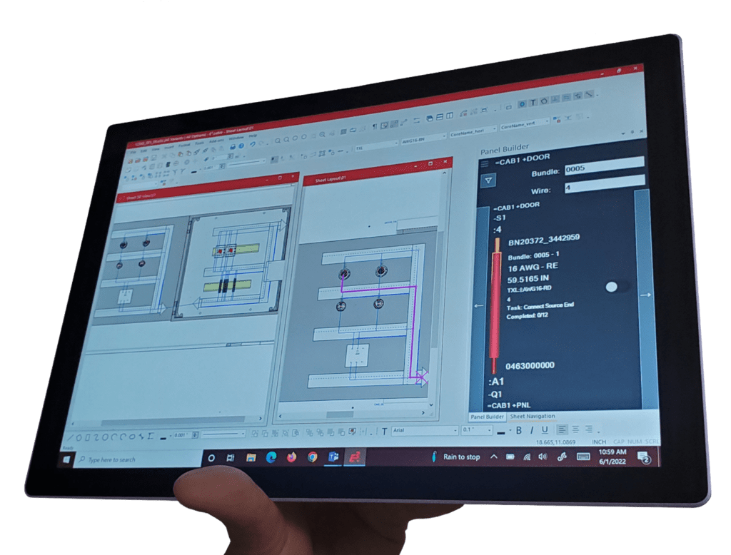
A modern manufacturing method includes providing technicians with handheld tablets on the shop floor to display and detail the build. Such devices are connected in real-time through Wi-Fi or Bluetooth and are directly connected to the design environment for instant feedback. When using the Wiring Tasks Manager in Panel Builder for E3.series, real-time job tracking is possible with an easy-to-use graphical interface that guides the user through the build process. This tracking allows teams to accurately determine the progress in the build process and forecast completion times based on previous performance. Furthermore, changes in the model or the design requirement are instantly visible on the shop floor, enabling production to handle multiple versions in a shared company database.
Empowering the Shop Floor with Assembly Tasks Manager
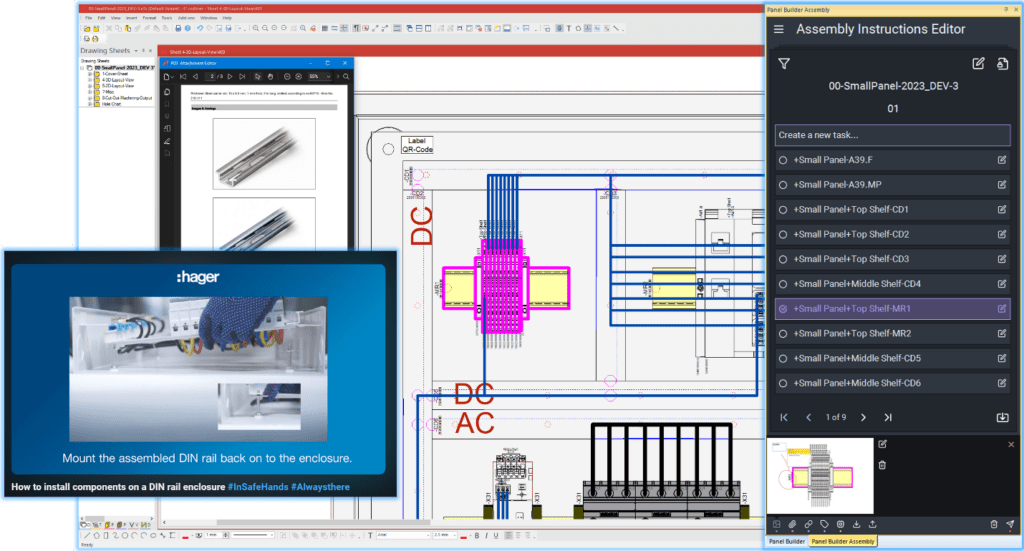
In short, the Assembly Tasks Manager, a tool within Panel Builder for E3.series, allows a designer to detail step-by-step manufacturing instructions to build the control panel quickly and easily. It’s the most modern technology for manufacturing shops looking to simplify assembly.
What else can we expect on the shop floor?
More paper? Maybe. If the company is small and not ready to take the next step, the Assembly Tasks Manager can print directly from the application for revision publishing. Even if a company sticks to paper instructions, the quality will be improved if they use a model to prove the design is right the first time.
What happens if the design changes?
The build process needs to adapt quickly to change. If the design changes, then a delta list is available.
In the design world where we currently work, some electrical parts are more complicated to source than others. Suppliers are having a much more challenging time locating some commonly used parts, so adapting quickly is essential.
E3.series can source an equivalent part that is available to purchase and is available for use now. Using the digital plug-in for tools manufacturing makes it simple to swap from an existing selected part to a similar part with equivalent functionality. The plug-in taps into online parts catalogs and stores, searching for only available parts.
How Can the Assembly Tasks Manager Simplify Your Engineering Workflow?
Nowadays, no one wants to spend time writing or typing detailed instructions. The general understanding in the engineering world is that very few people take the time to read the instructions thoroughly anyway! What is required is a simple process to relay the information to the assembly technician.
The Assembly Tasks Manager aids the engineer in generating a concise step-by-step set of detailed instructions. A simple plug-in window alongside the design holds simple tools like whiteboards for markup and data sheet access. It acts like a co-pilot, helping to direct the makeup of the manufacturing instructions. Videos or direct links to resources that help explain assembly can be assigned to parts of the design and saved away for reuse.
Benefiting from Shop Floor Automation
What Changed on the Shop Floor?
Productivity: Modern tools and digital models streamline processes and reduce manual tasks.
Time Savings: Automated tools and pre-built sub-assemblies speed production.
Accuracy and Efficiency: Digital models and algorithms ensure precise and efficient assembly.
Cost Reduction: Less waste and cleaner work environments lower costs.
Skilled Workforce: Simplified instructions reduce dependence on highly skilled labor.
Technology: Handheld devices improve progress tracking and forecasting.
Reproducibility and Scalability: Consistent instructions and scalable models support diverse project needs.
Simplified Instructions: Pictures, datasheets, or videos allow engineers to communicate assembly procedures, replacing lengthy text instructions.
By embracing these advancements, the shop floor evolves from a slow-change environment to a dynamic space where innovations lead to more efficient, accurate, and cost-effective manufacturing processes.

-
Product Director of E3.series
Paul Harvell Is the Product Director of E3.series. With 25 years experience working with electrical design solutions, Paul now focused on installation, implementation and training for Zuken's E3.series in different industry sectors ranging from small control panel application to vehicle wire harnessing and all the way up to power generation and distribution. He is also the architect and driving force behind the manufacturing tool, Harness Builder for E³.series.
- Blog
February 04, 2025
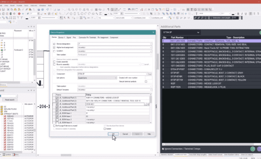
Tech Tip: How to Display Additional Parts in the Device Tree
e3-series, Electrical & Wire Harness, How to..., Tech-Tips, E3.series, E3.series 2025, Blog
- Blog
January 30, 2025
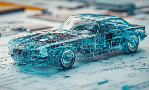
Transforming the Wire Harness Design and Optimization Process
Automotive, e3-series, Electrical, Electrical & Wire Harness, E3.series, Blog

- Webinar
January 22, 2025
Optimizing Wiring System Design
Webinar, Zuken USA, E3.series Release 2025, Control Panel Manufacturing Software
Wednesday, March 5, 2025 - 2:00 pm ET

- Blog
January 09, 2025
Top 10 Blog Posts of 2024
Americas, cr-8000, Data management, e3-series, Electrical & Wire Harness, PCB Design, 2023, CR-8000, E3.series, Electrical Design, PCB design, Top 10 Blogs, Blog
Related Products and Resources
- Blog
February 04, 2025
Tech Tip: How to Display Additional Parts in the Device Tree
e3-series, Electrical & Wire Harness, How to..., Tech-Tips, E3.series, E3.series 2025, Blog
- Blog
January 30, 2025
Transforming the Wire Harness Design and Optimization Process
Automotive, e3-series, Electrical, Electrical & Wire Harness, E3.series, Blog
- Blog
January 09, 2025
Top 10 Blog Posts of 2024
Americas, cr-8000, Data management, e3-series, Electrical & Wire Harness, PCB Design, 2023, CR-8000, E3.series, Electrical Design, PCB design, Top 10 Blogs, Blog
- Blog
January 07, 2025
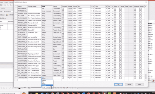
Tech Tip: How to Create Custom Attributes in E3.series
e3-series, Electrical & Wire Harness, How to..., Tech-Tips, E3.series Tech Tips, Tech Tip, Blog