What are 3 different types of electrical wiring diagrams?
Engineers and technicians use wiring diagrams as indispensable tools when understanding the intricacies of electrical systems. These diagrams visually show the connections of electrical components and the flow of electrical power through a system. However, creators don’t make all wiring diagrams or wiring schematics equal. Several types exist, each designed for a specific purpose or perspective. In this blog, we’ll delve into three primary diagrams: schematic, pictorial, and ladder diagrams. Let’s dive in!
Wiring Schematic Diagram:
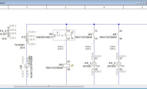
People in electronics or electrical engineering most commonly encounter these diagrams. So, what differentiates schematic diagrams, which some also call wiring schematics?
- Symbolic Representation: Schematic diagrams use standardized symbols to represent each component, rather than showing the actual appearance or physical layout. For example, unique characters represent resistors, capacitors, and switches.
- Logical Connections: This diagram type highlights the electrical connections of components, not their physical locations or real-world wiring setups.
- Functionality over Form: Focusing on connections and using symbols, schematic diagrams offer a clear view of a circuit’s operation without drowning in the wiring’s physical details.
Wiring Pictorial Diagram:
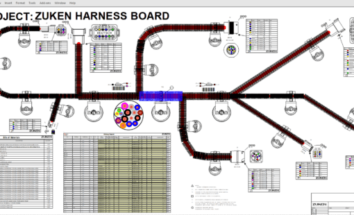
As the name indicates, pictorial diagrams strive to offer a more visual, authentic representation of electrical components and their connections.
- Real-World Perspective: Pictorial diagrams showcase components as they appear in reality, contrasting the abstract symbols in schematic diagrams. A graphical chart might, for instance, display an actual drawing of a resistor or plug.
- Ease of Understanding: Pictorial diagrams simplify comprehension, especially helpful for those unfamiliar with standardized symbols or those with a visual bent. DIY enthusiasts or electrical work novices often find them beneficial.
- Lack of Technical Detail: Pictorial diagrams sometimes struggle to detail complex circuits as effectively as schematic diagrams.
Wiring Ladder Diagram:
Primarily in the industrial sphere for control logic representation, ladder diagrams (or line diagrams) offer a distinct visualization method for electrical circuits.
- Parallel Lines Structure: Their name derives from their ladder-like appearance, with two vertical lines symbolizing power sources and intervening rungs that highlight various components and circuits.
- Sequential Logic: Each ladder diagram rung typically symbolizes a distinct operation or logic function, making process or operation tracking straightforward.
- Industrial Popularity: Industries, especially manufacturing, frequently use ladder diagrams because they depict complex machinery operations step by step.
Zuken’s E3.schematic:
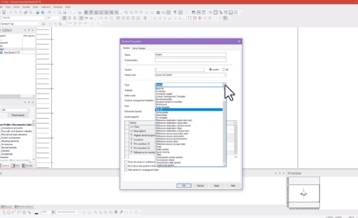
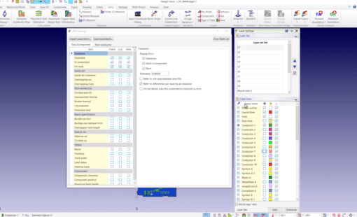
The demand for intuitive and accurate wiring diagrams has soared in our tech-dominated era. Software like Zuken’s E3.schematic delivers these intricate diagrams. At the evolution’s forefront, E3.schematic offers an all-encompassing solution for crafting sophisticated wiring diagrams. Professionals around the globe trust E3.schematic because it streamlines the design process while ensuring precision and efficiency.
In Conclusion:
Whether you’re studying electrical engineering, working as a professional technician, or nurturing an electrical curiosity, distinguishing these three diagram types can sharpen your insight into electrical systems. Each type has its distinct function, with the most suitable often hinging on the particular task. So, when you next encounter a wire diagram, you’ll recognize it immediately!
Related Products and Resources

- On-Demand Webinar
With the new Functional Design capability built into E3.series, Zuken introduces a new, integrated, solution for system design that integrates the creation of Block Diagrams with the generation of Interconnect Diagrams and System Wiring Diagrams.
- Products

- Products
E3.series is a Windows-based, scalable, easy-to-learn system for the design of wiring and control systems, hydraulics and pneumatics. The out-of-the-box solution includes schematic (for circuit and fluid diagrams), cable (for advanced electrical and fluid design), panel (for cabinet and panel layout), and formboard (for 1:1 wiring harness manufacturing drawings). Integrated with MCAD, E3.series is a complete design engineering solution from concept through physical realization and manufacturing output.
