A circuit diagram in electronics and electrical engineering visually represents an electrical circuit. This guide seeks to clarify the components and importance of circuit diagrams, providing insights for both beginners and experienced professionals in the field. Enthusiasts and engineers can readily use circuit diagrams for innovation, troubleshooting, and sharing complex electronic concepts by building and understanding of what they are and how they work.
What Is a Circuit Diagram?
First, let’s discuss what it is. Also known as an electrical, electronic, or schematic diagram, a circuit diagram graphically represents an electrical circuit. It employs standardized symbols to depict the various components within the circuit, like resistors, capacitors, wires, and transistors, among other things. Additionally, illustrating how electrical components connect serves as its primary purpose, offering a clear and concise method to visualize and comprehend the operations of an electrical device.
The Language of Circuit Diagrams
Second, let’s understand that learning a new language consists of symbols and lines representing various electrical components and their connections. The following are some critical elements:
- Symbols: A unique symbol represents each electrical component. For instance, a simple line might represent a wire, while a series of zigzag lines symbolize a resistor. Learning these symbols is crucial for interpreting and creating circuit diagrams.
- Connections: Solid lines represent electrical connections or wires between components. A line intersecting another line with a dot indicates a connection. Lines that cross without a dot signify that the wires do not connect.
- Power Sources: Symbols for batteries or power supplies are often found in circuit diagrams, indicating the electrical power source.
- Grounding: Grounding symbols are essential for safety and functionality, showing how the circuit connects to the earth.
Types of Circuit Diagrams
Diagrams range in complexity from simple diagrams illustrating basic circuits to complex schematics depicting intricate electronic systems. One can broadly categorize them into the following types:
- Schematic Diagrams: Detailed diagrams like these show the components of a circuit and their connections. It is typical to use these to design a Printed Circuit Board (PCB).
- Wiring Diagrams: Unlike schematic diagrams, wiring diagrams concentrate on a system’s physical connections and layout. Builders and automotive professionals frequently employ them in electrical systems. An electrical system typically consists of a wire harness cable or a control panel.
The Importance of Circuit Diagrams
These diagrams are invaluable tools in the field of electronics for several reasons:
- Visualization: They make it easier to understand and analyze by visually representing the construction of an electrical circuit.
- Communication: Circuit diagrams are a universal language that allows engineers and technicians worldwide to share and comprehend electrical designs without barriers.
- Troubleshooting: Illustrating the connections and components facilitates identifying and resolving issues within electrical systems.
- Design and Development: They are essential in the design process, enabling engineers to plan and iterate on electrical systems before physical construction.
How to Read Circuit Diagrams
Reading them requires familiarity with the symbols and an understanding of some of the generic symbols used in a design. Here are some steps to get started:
- Identify the Symbols: Symbols can be components purchased from a component supplier or a generic symbol like a resistor, power, and ground.
- Look for Labels: Labels are used to identify the type of component (e.g., R means resistor) with a number and value specifying the resistance. Labeling standards are typically used.
- Understand the Connections: Pay attention to how the components are connected. Connections are usually identified with a signal name ( e.g., +5VCC or GND). The signal name usually provides insight into the purpose of the connection. The connections typically translate to a physical wire or a trace on a PCB.
Creating Your Circuit Diagrams
Creating these diagrams can be a rewarding experience, allowing you to bring your electrical designs to life. Here are some tips for creating your own:
- Use Software: Various software tools can help you create professional-looking circuit diagrams. These tools often come with libraries of symbols and functionalities to test your circuits virtually.
- Start Simple: If you’re new to creating, then start with simple circuits and gradually work up to more complex designs.
- Check Your Work: Ensure your diagram accurately represents the connections and components of your circuit. Mistakes in a diagram can lead to confusion or errors in the actual circuit.
Integrating with Zuken’s Advanced Solutions
Zuken’s E3.series: A Comprehensive Tool for Wiring, Control Systems, and Fluid Engineering
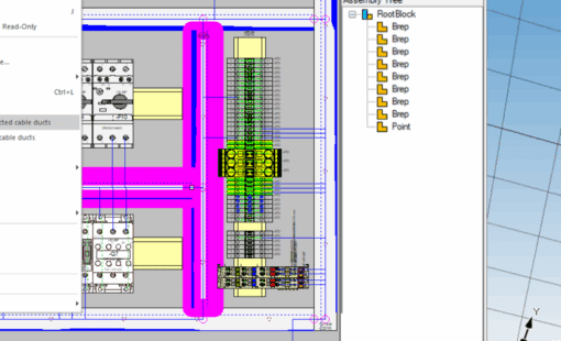
Zuken’s E3.series is a robust and versatile software suite for electrical wiring, control systems, and fluid engineering projects. It excels in managing circuit diagrams for various applications, from automotive to industrial machinery. Moreover, with its intelligent component-based design, E3.series simplifies creating detailed and accurate circuit diagrams, ensuring compliance with industry standards and facilitating easy modifications.
- Automated Documentation: Automatically generate detailed documentation for your circuit diagrams, including bill of materials (BOM), wire lists, and reports, streamlining the transition from design to production.
- Collaborative Design Environment: E3.series supports collaborative efforts, allowing multiple users to work on a single project simultaneously. This feature is crucial for large-scale projects requiring teamwork and synchronization.
Zuken’s CR-8000: Pushing the Boundaries of PCB Design
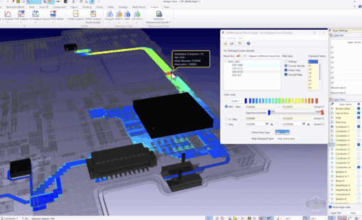
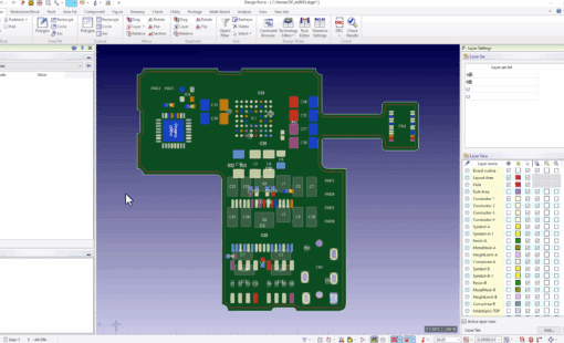
CR-8000 is Zuken’s flagship solution for PCB design, offering a comprehensive suite of tools that cover the entire development cycle, from concept to manufacturing. It’s specifically engineered to tackle the challenges of multi-board design, enabling engineers to optimize circuit diagram integration into physical PCB layouts.
- Advanced Design Capabilities: With CR-8000, users can transition from circuit diagrams to PCB layout, incorporating sophisticated routing strategies, 3D modeling, and electromagnetic interference (EMI) analysis.
- System-Level Design Integration: CR-8000 excels in system-level design, allowing for the integration of circuit diagrams with mechanical and software components. This approach ensures that all aspects of product development are aligned, therefore reducing time to market and enhancing product reliability.
The Zuken Advantage: Enhancing Circuit Diagram Efficiency
Integrating circuit diagrams with Zuken products offers numerous advantages. Among them, improved design accuracy and efficiency, and enhanced collaboration and communication among project teams. Additionally, Zuken’s software solutions are tailored to meet the changing needs of the electronics industry, providing the crucial tools needed to turn innovative ideas into tangible outcomes.
- Seamless Integration: Zuken’s products support seamless integration with other CAD tools and engineering software, facilitating a smooth workflow from the circuit diagram to the final product.
- Comprehensive Support and Training: Zuken provides extensive support and training resources, ensuring users can maximize the potential of their software to create, analyze, and optimize circuit diagrams.
Conclusion: Empowering Innovation with Zuken
Converting the circuit diagram into something real can be challenging, involving design rule checking, manufacturing outputs, and the supply chain. By leveraging Zuken’s comprehensive tools, professionals can transcend traditional design limitations, ushering in a new era of innovation and efficiency in electrical and PCB design. Whether you’re a seasoned engineer or an electronics enthusiast, Zuken offers the tools and resources to transform your circuit diagrams into real-world solutions.


