Unified Product Evolution with Advanced Life Cycle Tools
Bridging Gaps Across the Product Life Cycle Stages with E3.HarnessAnalyzer
E3.HarnessAnalyzer plays a pivotal role in enhancing product quality and simplifying advanced analysis, even for those without extensive design knowledge throughout the product development life cycle. All stakeholders involved in engineering, procurement, manufacturing, quality, and service, including OEMs and suppliers, can utilize this tool. With its ability to visualize harness modules, calculate critical metrics, and facilitate thorough design reviews through 3D models and schematic information, your team can ensure precision and efficiency. The software has the ability to manage complex analyses, like bundle diameters and wire weights. Additionally, it fosters collaboration through integrated redlining and tracing design dependencies, making it easy to maintain high standards throughout the product life cycle stages.
Addressing Current Challenges Throughout the Product Life Cycle
Design teams, manufacturers, and field technicians in the engineering industry often face significant challenges with the traditional reliance on paper schematics and the complexities of troubleshooting modern electrical machines. This approach leads to inefficiencies. For example, the time-consuming process of manually searching through stacks of paper to find the correct version of a schematic. Another issue is the difficulty in visualizing how changes affect the overall design. On top of that, pinpointing issues within complex systems becomes even more challenging without a dynamic, interactive tool. This traditional approach hampers productivity, increases the risk of errors, and slows the troubleshooting process. As a result, this calls for a more integrated and digital solution.
Challenges in the Design Definition and Review Product Life Cycle Stage
Electrical designers are facing significant challenges in today’s complex projects. Verifying entire systems can feel overwhelming due to the intricate interconnections and functionalities. And let’s not forget about managing multiple data sources and ensuring consistency throughout the process – it’s definitely not a walk in the park! But that’s not where the challenges end. Traditional methods, such as hand-written redlines for design changes, further complicate the revision process. Additionally, the necessity for interdisciplinary collaboration introduces communication and workflow synchronization hurdles. Different teams may use varied tools and methodologies, which makes project execution quite chaotic.
Manufacturing and Service Stage Challenges
Manufacturers and service technicians grapple with significant hurdles in their workflow as well. On the manufacturing front, reliance on paper schematics and limited tools on the production line complicates the process, resulting in manual quality assessments being challenging. Field technicians face challenges when troubleshooting complex electrical machines. Access to 3D representations is crucial for accurate harness routing and assembly. Without this access, technicians may struggle to diagnose and resolve issues efficiently. These constraints underscore the need for more advanced digital solutions to streamline manufacturing and maintenance processes.
E3.HarnessAnalyzer to the Rescue
E3.HarnessAnalyzer is a sophisticated tool designed to revolutionize how electrical harnesses are designed, manufactured, and serviced. By offering comprehensive features, it streamlines the product life cycle workflows and enhances the accuracy and efficiency of electrical projects. Some of these key features include:
-
Design Tools:
-
- Visualizing modules: Provides on-demand visualization of different feature-based harness modules and configurations. As a result, this makes it simple for users to see what components are relevant to a module. Additionally, users can create module-based bills of materials and run module comparisons.
-
- Distance calculations: It is easy to verify the quality of the harness with calculated distances from selected segments or objects based on the design.
-
- Wire resistance calculations: Quickly determine the direct current resistance of a selected wire, taking length, conductor material’s resistivity, and temperature into account. This calculation can assist with verifying correct wire size usage.
-
- Bundle diameter calculations: Using these capabilities, users can plan accurately for different module variations. Moreover, with the scenario analysis tools, users can add or remove wires to test the impacts on the bundle diameters.
-
- Weight calculations: The weight calculator allows for calculating the weight of a selection of wires or conductors. Length and certain specifications like material are taken into account for this calculation. Module weight calculations are also available and provide an accumulated weight of the module components.
-
- Splice location proposal: Receive guidance on relocating splices. The splice location proposal tool evaluates and verifies the best position of a splice by taking the used conductor volume as a reference value.
-
Design Verifications and Checks:
-
- Inliner consistency reporting: Using a tool like the inliner consistency reporting helps to validate that the inline connectors have matching wire color, size, type, signal, and terminal plating. Automating this process is a great time and quality improvement to the traditional checks done manually.
-
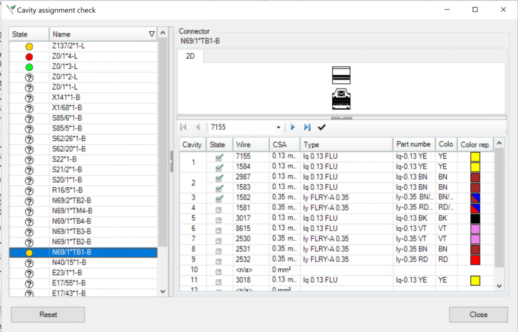
- Cavity Assignment Checks: This check provides a verification process for the cavity content of each connector; for example, the user can check the wire cross-section and color, and the checker can document the resulting state.
-
- Ultrasonic Splice-Terminal Distance: Companies can set a design rule specifying the minimum wire length from specific terminals to an ultrasonic processed splice. The splice to terminal distance check provides an automatic way of discovering any instances breaking this rule before it causes issues downstream.
- Analysis Views: These options provide users with quick views of critical technical details across the design life cycle. Users can easily highlight the design details, such as a harness’s dry or wet environment, eyelets, terminals with a selected plating material, splices, and more
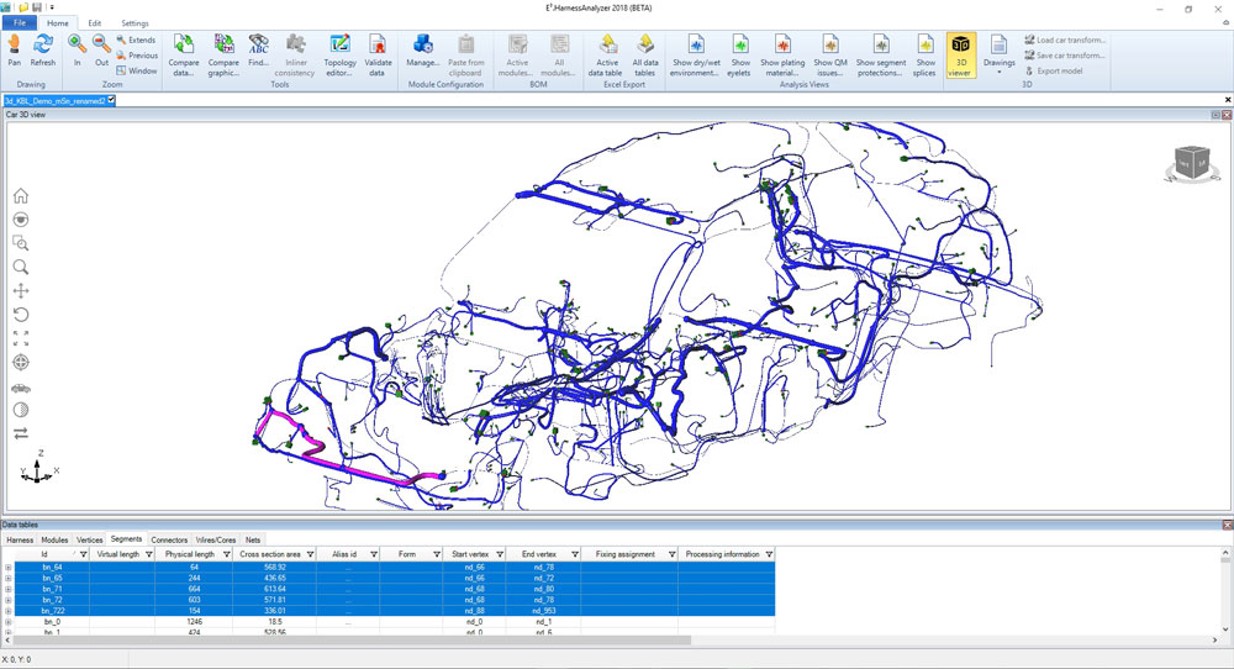
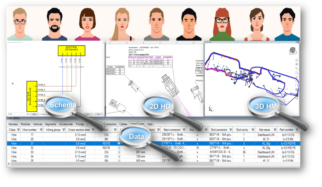
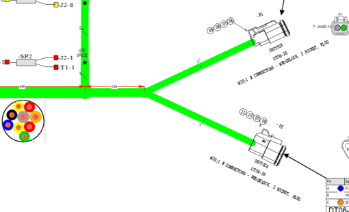
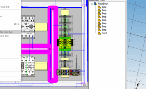
- 2D/3D Visualization: With the option to visualize the vehicle wiring harnesses in 2D or 3D, all stakeholders can work in the environments they are most comfortable with without needing to be CAD experts. Additionally, these system-wide 3D visualizations can include all harnesses and vehicle geometry for real-world accuracy.
-
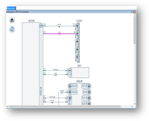
Schematic Browser: The Schematic Browser tool automatically creates schematics based on logical information. The Schematic Browser tool makes it easy for service technicians to highlight and trace connectivity in the design. With the ability to start from various entry points, users can expand on the connections from any module, component, or wire for enhanced data access. Additionally, the interface is simple and intuitive to use, so there is no need for in-depth training on using the tool. Users can identify inline connectors and visualize the complete system when loading all vehicle harnesses.

The Schematic Browser makes it easy to trace connectivity throughout the design. -
Document Review and Redlining:
-
- Redlining: Both internally or with suppliers, collaboratively provide detailed comments, categorize error types, and trace the entire error cycle through discovery, correction, and validation for improved design accuracy.
-
- Version Comparison: Produce detailed and visual comparisons to understand changes made across versions.
-
Quality Tools:
-
- Quality Stamping: Users can use the Quality Management stamping function to define tests or checkpoints, for example, regarding dimension information. A marker is shown on the drawing to specify the corresponding test entry. Link QM stamps to objects like segments, fixings, and connectors, or they can be placed freely on the drawing and are automatically related to the harness.
-
- Quality Issue Reporting: Quality teams communicate quality concerns to address by loading a report file to classify and visualize the quality issue content within the drawing.
- Use on the go: All functionality is available for designers and technicians on the shop floor or in the field to use on a tablet.
E3.HarnessAnalyzer addresses current industry challenges by offering a dynamic, user-friendly platform for all harness design and maintenance phases in the product life cycle.
E3. HarnessAnalyzer’s Impact Across the Product Life Cycle Stages
E3.HarnessAnalyzer significantly enhances the product life cycle, from design to service/maintenance. During the design phase, the team can thoroughly review all technical details with precise visualization and analysis features. During manufacturing, it streamlines production by calculating bundle diameters and weights and visualizing harnesses in 3D to reduce errors. When it comes to service and maintenance, E3.HarnessAnalyzer’s browsing and 3D visualization features simplify troubleshooting and repairs. This tool has integrated redlining and efficient search functions. It makes communication across teams and with suppliers a breeze. It eliminates the need for multiple tools and fosters a more cohesive workflow.
End of the Line
E3.HarnessAnalyzer offers transformative benefits for engineering data management across the design to maintenance spectrum. Its capabilities for improved analysis, testing, and support streamline workflows, enhance accuracy, and facilitate collaboration. Moreover, providing tools for on-demand visualization, comprehensive technical checks, and efficient troubleshooting eliminates the need for multiple platforms. Teams can manage data more cohesively and effectively. E3.HarnessAnalyzer boosts productivity and significantly improves project outcomes by ensuring the optimization of every phase of the engineering process for success.
Give us a shout-out to learn more about how you can leverage E3.HarnessAnalyzer and take your productivity to the next level!

-
Application Engineer

Nick Norris is an application engineer for the professional services team. Nick works closely with customers helping them implement new tools, particularly those aiding in the bridge between the MCAD and ECAD worlds. Outside of work, not only does Nick enjoy teeing off and spending time on the green, but he is also a coffee enthusiast.
- Blog
- Blog

- Blog
- Blog