
Validating the Ever-Complicated CAN Bus Design for Wire Harness Engineers
Elevating the Art of CAN Bus Design Validation
Let’s face it, designing an electrical CAN bus is becoming more complicated by the day. It seems any machine that moves now requires these types of buses as part of its electrical system design. On top of that, as we trend further with automated driving and battery-powered powertrains, the need for the next generation of higher speed/higher data CAN is knocking at the door. Validating CAN bus designs is more important than ever; however, this is still a manual process for wire harness engineers.
What is a CAN Bus?
A CAN bus (or Controller Area Network) is a network for electronic control modules to communicate with each other within a vehicle or machine system. The key to CAN bus technology is its ability to handle multiple microcontrollers within a single network without using a host computer. This technology makes it a fundamental component of modern automotive design. Several variants of the CAN bus are being used today, which differ in speed and data size. The most commonly used variants are low-speed and high-speed CAN. The flexible data rate CAN is becoming more popular for EV and ADAS applications. Recently, CAN XL was standardized to handle extreme data sizes and speeds for future purposes.
Why Use a CAN Bus?
Electrical architects prefer the CAN bus system in environments where reliability and robustness are critical. The technology’s design ensures optimal functionality in the noisy electrical environments typical of automobiles and industrial machinery, where other systems might fail. This resilience, coupled with the ability to significantly reduce wiring complexity, makes the CAN bus ideal for automotive, industrial automation, and medical equipment applications.
What is the Importance of CAN Bus?
Integrating CAN Bus systems in automotive design has dramatically enhanced vehicle safety and functionality. Advanced features that improve driver safety and comfort, such as parking assist, adaptive cruise control, and lane assist/collision avoidance systems, rely on the seamless function of the CAN bus to operate effectively. CAN bus utilizes a single point of entry that allows a user to connect and communicate with the system. We use this communication to diagnose problems occurring in a vehicle or machine system quickly.
Why do you need CAN Bus Design Validation?
Since the CAN bus is essential to a vehicle’s overall operation, you would expect to meet specific design standards during the design stage. Various CAN bus standards are available from SAE and ISO for each type of network. Additionally, even individual OEMs create their own design guidelines to keep CAN bus designs within specifications. Validating a complete CAN bus design against these specifications is where the process gets tricky. Since a CAN bus touches multiple electrical subsystems, validating the network to design specifications can be challenging when the process has been manual for so many years.
Utilizing Zuken’s Bus Checker for E3.series for CAN Bus Design Checks
Bus Checker for E3.series allows wire harness design engineers to run design rule checks (DRCs) for bus systems within their projects. Users can configure the settings to focus on finding and checking the design requirements of all the CAN bus variants. Therefore, they can run these DRCs to ensure the design complies with the different CAN specifications.
What Checks are Available in the Tool?
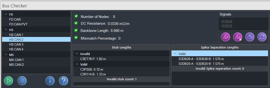
For a selected bus, Bus Checker will run the following calculations:
Number of Nodes
The tool verifies that the number of nodes connected within a CAN bus is below the maximum amount, according to specifications. A node typically comprises an ECU (electronic control unit) or control module.
Backbone Length
Bus Checker will find the longest run between two terminating nodes and verify that it is less than the maximum amount permitted to be compliant. This calculation works by starting with one terminating node and following the circuit, adding length until it encounters another terminating node. When a splice interrupts this flow, the tool will evaluate which path to continue for the backbone.
Stub Length
The Bus Checker tool runs additional length checks on the stubs off the main backbone. A stub connects the module (terminating node) to the backbone via a splice or double termination. Each stub length is calculated and categorized as valid or invalid based on whether it meets the thresholds specified for that network type.
DC Resistance
Another helpful check that Bus Checker can perform for you is calculating whether the wires meet the specifications for DC resistance. A wire’s DC resistance depends upon its length, cross-sectional area, and the resistivity of the center conductor. Since E3.series has each wire’s length and cross-sectional area, the tool can quickly automate this calculation and report failures.
Mismatch Percentage
Checking for mismatches in the wire lengths of CAN-High (CAN-H) and CAN-Low (CAN-L) in a CAN Bus system is crucial for several reasons. Primarily, the checks ensure reliable and efficient communication across the network. CAN Bus systems use a differential signal to communicate between devices. Where the CAN-H and CAN-L wires carry inverse voltages, this setup helps reduce noise. Additionally, it ensures robust communication, especially in environments with high electromagnetic interference, which is common in automotive and industrial settings. The Bus Checker compares the lengths of CAN-H and CAN-L wires in a CAN Bus system against the specified allowance.
Splice Separation Lengths
The splice separation lengths or star topology requirement is to check the distance between any two consecutive splices. This check ensures that there is more than a defined distance for that network type. Bus Checker identifies the location of two consecutive splices and calculates the distance between them. The tool then lists any valid or invalid wires that run between the splices in the table.
Additional Features of the CAN Bus Checker Tool
In addition to the various checks, Bus Checker has additional functionality available to highlight buses (both the entire CAN bus and just the backbone), which helps visualize the CAN bus across multiple sheets. The Output Nodes button lists all the bus nodes for the project in the Messages pane. A user can then use the jump link to open the related drawing sheet with the selected node highlighted. Similar messages are available when you double-click on an invalid bus length or splice separation length to display a list of the invalid items in the Messages pane. From there, you can jump to the related item in the drawing.
Making CAN Bus Design Validation a Breeze
In a nutshell, the CAN bus system plays a vital role in both automotive and industrial settings due to its robustness, reliability, and streamlined wiring capabilities. As technology advances, thoroughly evaluating CAN bus designs becomes increasingly critical. Tools like Zuken’s Bus Checker for E3.series enable us to streamline this process and ensure adherence to CAN specifications. This allows us to stay at the forefront of industry standards. In addition, it enhances the efficiency and safety of vehicle systems, which is pivotal for the future of car design.
For more detailed information on Bus Checker for E3.series, visit our website.

-
Applications Engineer at Zuken USA

Justin Schemanske is an Application Engineer who helps customers by showcasing E3.series products, providing implementation support, and providing tool-related coaching. Outside the office, Justin is an avid golfer—however, he would be the first to admit that he isn’t very good at golf.

- Blog
- Blog

- Blog
- Blog
Related Products and Resources
- Blog
- Blog
- Blog
- Blog