Ensure Accuracy and Efficiency in Product Development
Simulation and verification tools allow engineers and designers to virtually test and validate their designs before building physical prototypes. Using these tools, developers can identify potential issues early in the design process, reduce the number of physical prototypes needed, and ultimately accelerate the time to market. With the increasing complexity of modern products and the pressure to bring them to market quickly, simulation and verification tools have become indispensable in ensuring that products are safe, reliable, and cost-effective. The E3.series tool suite offers several tools to run verification and simulations on the project designs.

Bus Validation
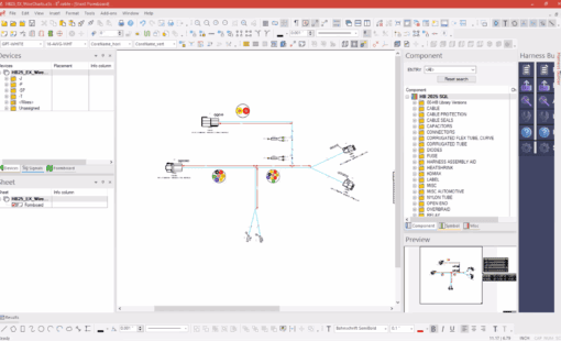
Zuken’s Bus Checker for E3.series empowers wire harness engineers to perform automated design rule checks (DRCs) tailored specifically for bus systems. Designed to ensure compliance with a wide range of CAN bus specifications, this tool allows users to configure checks that meet the precise needs of their projects, enhancing the reliability and performance of their designs.
For any selected bus, the Bus Checker performs a series of critical calculations to verify design integrity:
- Number of Nodes: The tool ensures that the number of nodes, typically including ECUs or control modules, does not exceed the maximum specified for the bus.
- Backbone Length: By calculating the longest run between two terminating nodes, the Bus Checker confirms that the backbone length stays within allowable limits. It intelligently navigates splices and evaluates the optimal path to determine compliance.
- Stub Length: Additional checks are performed on stub lengths, connecting nodes to the backbone. Each stub is assessed to ensure it meets the network-specific thresholds for valid connection lengths.
- DC Resistance: Leveraging data on wire length and cross-sectional area, the tool calculates DC resistance to verify that it aligns with bus requirements, flagging any deviations for quick resolution.
- Mismatch Percentage: To ensure robust communication and minimize noise, the Bus Checker compares the lengths of CAN-High and CAN-Low wires, ensuring they fall within the specified tolerance for differential signal transmission.
- Splice Separation Lengths: The tool checks the distances between consecutive splices, crucial for maintaining proper star topology. It identifies and flags any invalid configurations to help you optimize your design.
The Bus Checker offers additional features to streamline your workflow:
- Highlighting Capabilities: Visualize the entire bus or just the backbone across multiple sheets, making it easier to manage complex designs.
- Output Nodes: The Messages pane provides a list of all bus nodes within your project. With the click of a button, you can jump directly to related drawing sheets.
- Error Navigation: Quickly identify and correct issues. Double-clicking on an invalid bus length or splice separation length displays a list of problematic items, allowing you to navigate directly to the relevant sections in your drawings.
Digitally Assisted Commissioning
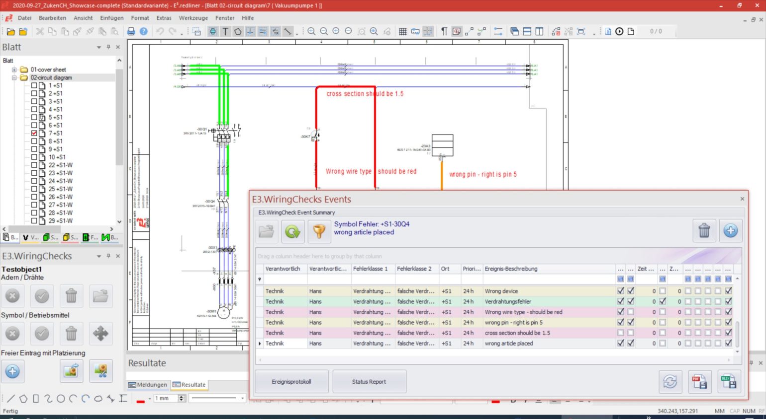
E3.WiringChecks supports testing a fully wired machine, vehicle, or control cabinet before or during the commissioning phase. Document the testing results as part of the E3.series data record. All relevant departments, from engineering to production, can access the error descriptions and assign issues to correct. With the data, teams can create a controlled process for error correction and follow-up checks.
- Digital recording and documentation of the testing of wiring and equipment
- Capture description of errors and documentation within the circuit diagram
- Document testing results as part of an E3.series project
DC Functional Analysis and Circuit Checks
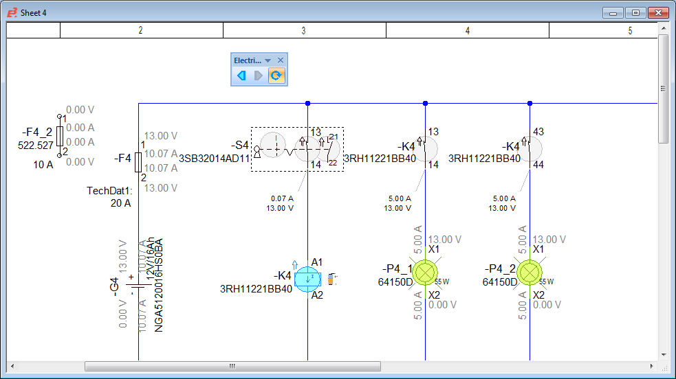
E3.eCheck is an extension to E3.series that enables users to functionally analyze their electrical schematic circuits and check designs for fuse and wire sizing errors. The utility works in real-time and provides instant feedback on the operability of the circuit design.
- Ideally suited for engineers and designers working with DC control systems
- For automotive, aerospace, railway, and special-purpose vehicle applications
Special objects exist in the E3.series library to facilitate functional checks, including power sources, fuses, switches, complex devices, and loads. Power supplies allow the user to stimulate the circuit while fuses monitor the inline current. Activate switches to allow current to pass between contacts and configure complex devices such as relays to open or close auxiliary contacts based on the coil operation.
Constantly monitor the current value and direction at pin level during the analysis and design phase. Observe the voltage drop at each pin to determine the effectivity of the circuit. Inline fuses will fail should their tolerance be exceeded. These checks allow users to correct designs during the prototype or development phase – before products enter manufacturing.
The voltage and current passing through the circuit control switches and contacts within the design. Energizing a coil will open and close auxiliary contacts, enabling or disabling current flow in other design sections, resulting in a simulation of the real-life operation of the circuit. As current passes through to the load, the voltage from objects such as lamps or motors are checked. Then the success or failure information is fed back to the user.
E3.eCheck complements the comprehensive capabilities of E3.series. With its electrically-aware component library, specifically-designed kernel, and numerous design rule checks, it is optimized for electrical design. The automatic selection of mating connectors, connector pin terminals, and cavity seals, and the prevention of short circuits and incorrect part usage ensures that correct design data is always available for manufacturing.
Wire Harness and Fluid Modeling and Simulation
E3.SaberFrameway integrates Synopsys’ Saber simulator with E3.series. E3.SaberFrameway enables design engineers to create right-first-time robust wire harness and fluid designs, helping them address growing project complexity and time/quality constraints through early access to virtual prototyping results. The solution directly integrates the multi-domain simulation of cables, wire harnesses, hydraulics, and pneumatics with Synopsys’ Saber® Simulator, in addition to the benefits for the design engineer, E3.SaberFrameway will also save time for specialist simulation engineers.
- Allows simulation engineers using Saber to perform accurate system-wide verification with E3.series project data
- Saves time by enabling E3.series project data to be used directly in the Saber simulator, thereby eliminating the need to re-enter the project data into the simulation environment
- Reduces time spent and the potential for errors by eradicating the need to send design updates manually between the simulation engineer and the design engineer
- By using E3.cable library data for simulation in Saber, eliminate inaccuracies in a simulation that occurs when separate libraries are out of date or not fully synchronized
- Enable/disable objects for simulation
- Show/modify simulation attributes
- Modify netlist settings
- Highlight active objects for simulation
- Update simulation parameters from parts gallery
- Launch Saber Help (Saber Book)
- Cross-probe with Saber
- E3.series symbol library
- Around 2,000 symbols aligned with Saber Parts Gallery
- Switch between evaluating logic or wired connections
Related Products & Resources
- Webinar

- Blog


